
Eureka
For R&D, Eureka makes reading and utilizing patents & technical documents easy.
Eureka AIR
Designed for self-driven R&D workflows. Generate viable solutions, solve complex R&D challenges, empower your innovation with AI.

Eureka Materials
Designed for material experts only. Revolutionize your material R&D, from search, analyze, to developing new materials.

TechResearch
Generate reliable direction feasibility study reports for your R&D in just a few steps.

TechSeek
Discover and master advanced knowledge NOW. Basics, ideas, possibilities, all at once.

TechMind
As an expert in R&D Theories, TechMind can generates customized viable solutions instantly.

TechRisk
Analyze your overall solution with one click, know your potential R&D risks in advance.

TechMonitor
Get weekly tech updates, stay abreast of the latest tech innovations and key insights.
Ultrasound diagnostic apparatus and signal processing method thereof
- Summary
- Abstract
- Description
- Claims
- Application Information
AI Technical Summary
Benefits of technology
Problems solved by technology
Method used
Image

Examples
first embodiment
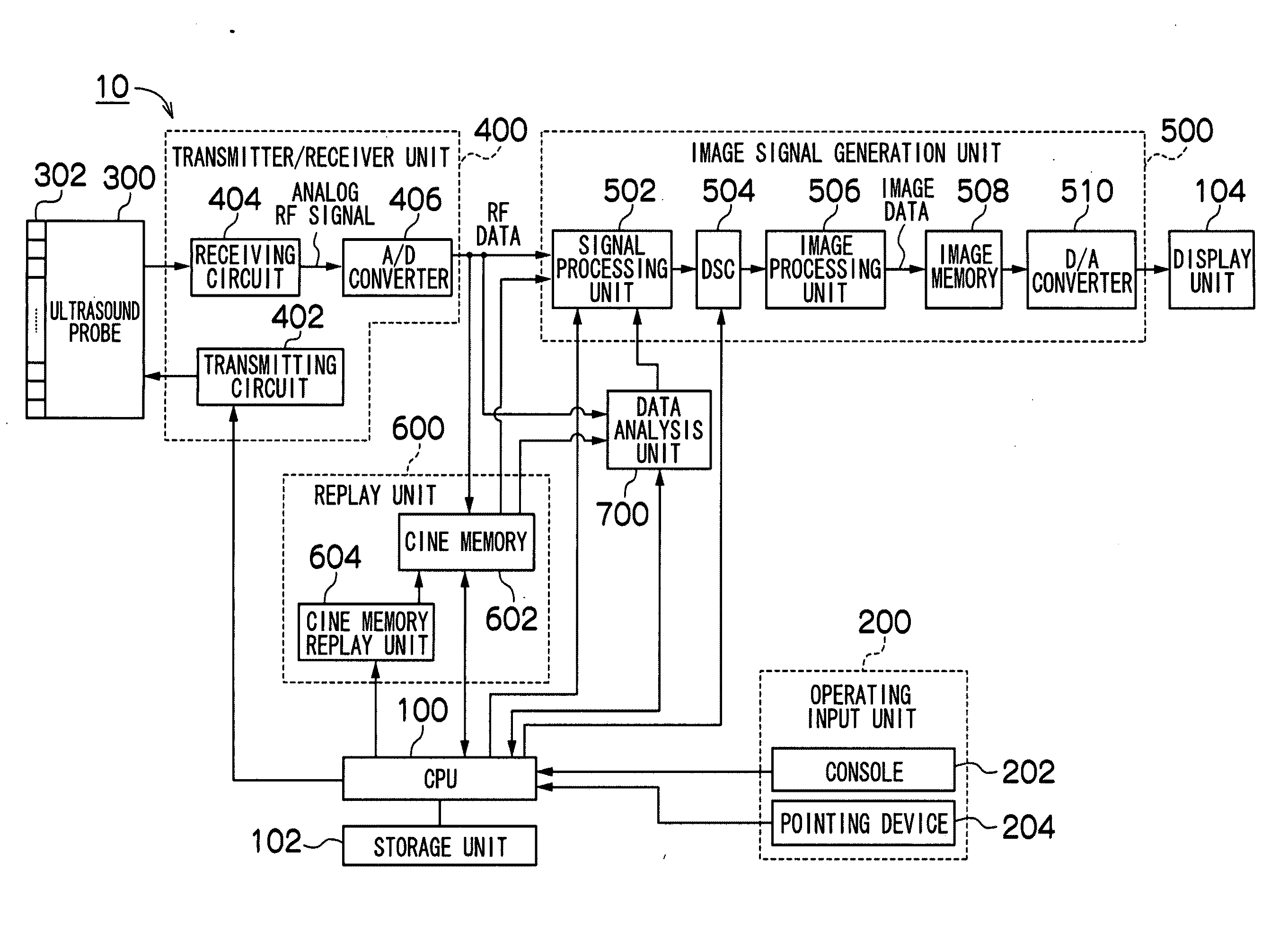
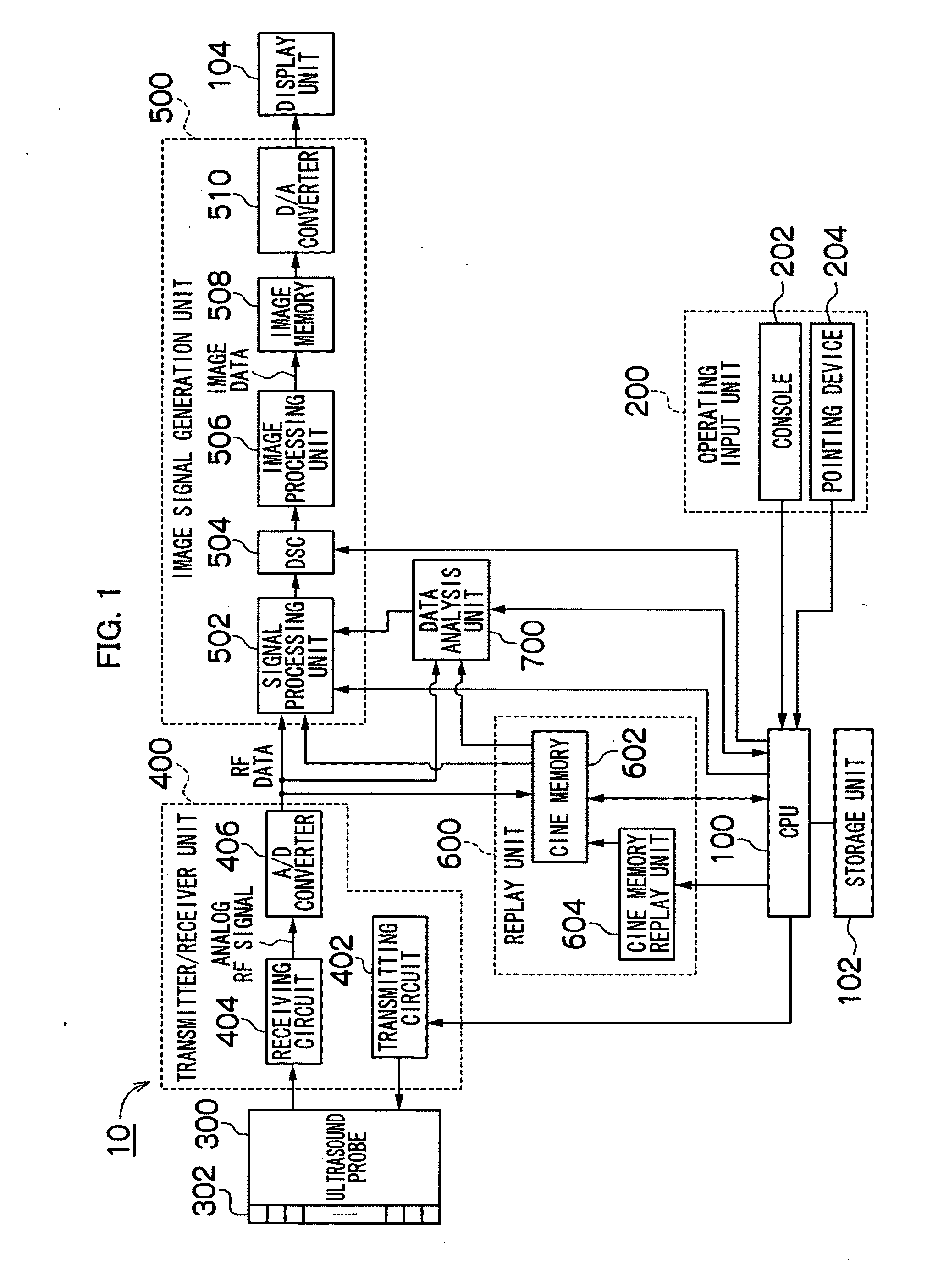
[0044]FIG. 1 is a block diagram illustrating an ultrasound diagnostic apparatus according to a first embodiment of the presently disclosed subject matter. An ultrasound diagnostic apparatus 10 illustrated in FIG. 1 transmits ultrasound beams from an ultrasound probe 300 to a object OBJ, receives ultrasound beams reflected by the object OBJ (hereinafter referred to as ultrasound echoes), and creates and displays an ultrasound image from a detection signal of the ultrasound echoes.
[0045]A CPU (Central Processing Unit) 100 controls the respective blocks of the ultrasound diagnostic apparatus 10 according to an operating input from an operating input unit 200.
[0046]The operating input unit 200 is an input device adapted to accept an operating input from an operator and includes a console 202 and a pointing device 204. The console 202 includes a keyboard for accepting an input of textual information (for example, patient information), a display mode changeover button for switching a disp...
second embodiment
[0088]A second embodiment is the same in configuration as the first embodiment and differs therefrom only in processing at the data analysis unit. Therefore, only the difference will be described.
[0089]FIG. 8 is a flowchart illustrating flow of processing by a data analysis unit according to the second embodiment of the presently disclosed subject matter. In addition, FIGS. 9 and 10 are drawings used to explain the processing of FIG. 8.
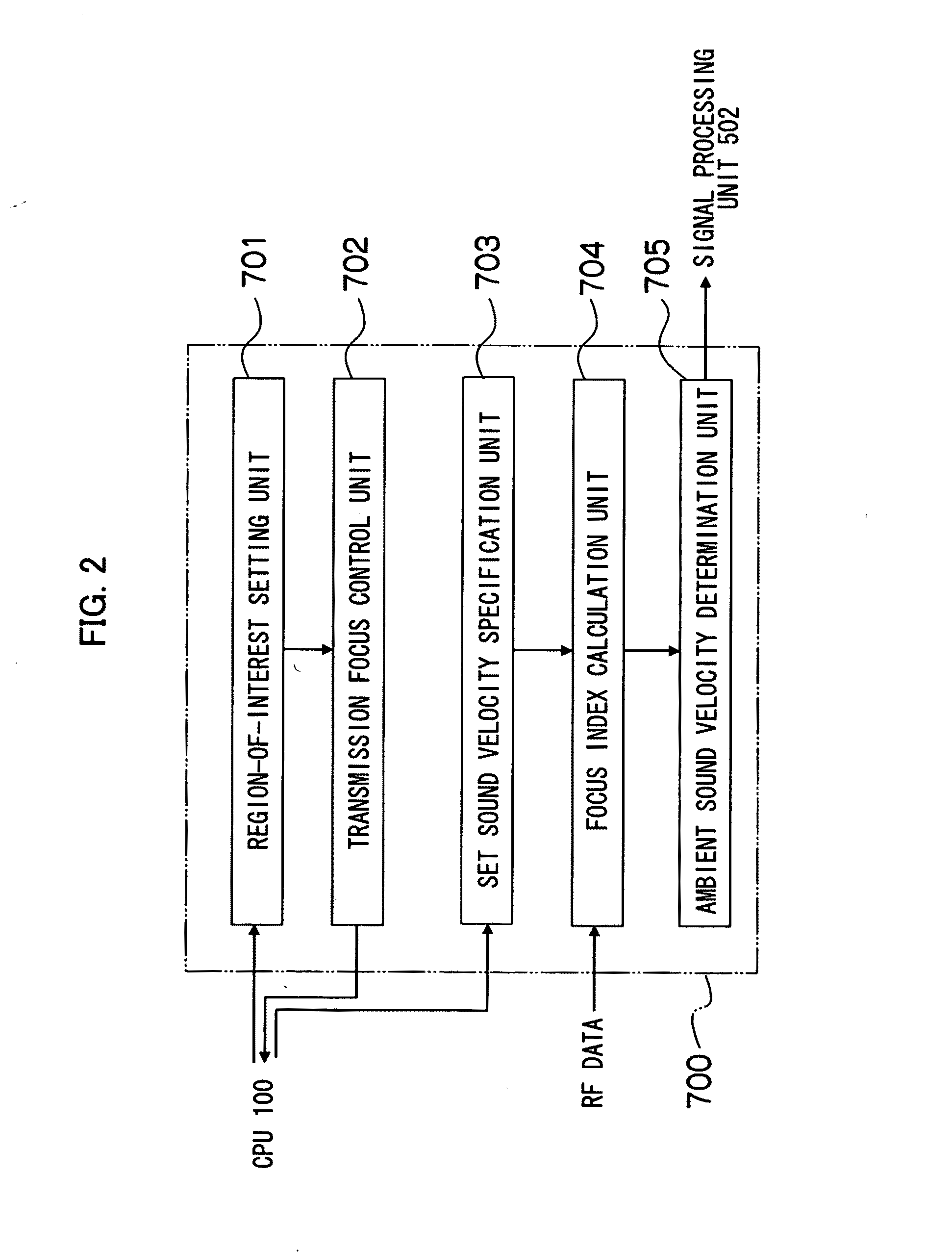
[0090]As illustrated in FIG. 8, a data analysis unit 700 sets the starting number Nst and the ending number Nend of a parameter N by a region-of-interest setting unit 701, following processing in step S10 (step S11). Then, the data analysis unit 700 sets the starting number Nst in the parameter N (step S31), following processing in step S30.
[0091]In the present embodiment, when an operator specifies a region of interest for RF image data obtained by, for example, a line-by-line method, the data analysis unit 700 causes the region-of-interest setting u...
third embodiment
[0104]A third embodiment is configured to utilize only a frequency spectrum shape, without including image intensity, in order to determine an ambient sound velocity from a line image.
[0105]That is, by determining an ambient sound velocity only from a spatial frequency spectrum shape in an azimuthal direction, without including image intensity, for the abovementioned line image (RF image data created by executing reception focusing assumptive of point reflection), it is possible to determine the ambient sound velocity of a speckle more precisely, compared with a conventional method for determining the ambient sound velocity from a line-by-line image.
[0106]Hereinafter, this mechanism will be described in detail.
[0107]In general, the point reflection (PSF) of an ultrasound image involves a variation in the characteristics of both “image intensity” and “frequency spectrum shape,” depending on a set sound velocity, as has been already described using FIG. 7. Hence, the ambient sound vel...
PUM
 Abstract
Description
Claims
Application Information
 - R&D Engineer
- R&D Manager
- IP Professional
- Industry Leading Data Capabilities
- Powerful AI technology
- Patent DNA Extraction
Browse by: Latest US Patents, China's latest patents, Technical Efficacy Thesaurus, Application Domain, Technology Topic, Popular Technical Reports.
© 2024 PatSnap. All rights reserved.Legal|Privacy policy|Modern Slavery Act Transparency Statement|Sitemap|About US| Contact US: help@patsnap.com