Power conversion control apparatus

Active Publication Date: 2011-04-07
DENSO CORP
View PDF13 Cites 67 Cited by
  • Summary
  • Abstract
  • Description
  • Claims
  • Application Information

AI Technical Summary

Benefits of technology

[0012]According to the present invention, there is provided a power conversion control apparatus for a power conversion circuit having the structure in which a plurality of series connections of a high-s

Problems solved by technology

However, the conventional power conversion control apparatus described above has a problem in that the process of discharging th

Method used


Image

  • Power conversion control apparatus
  • Power conversion control apparatus
  • Power conversion control apparatus

Examples


first embodiment

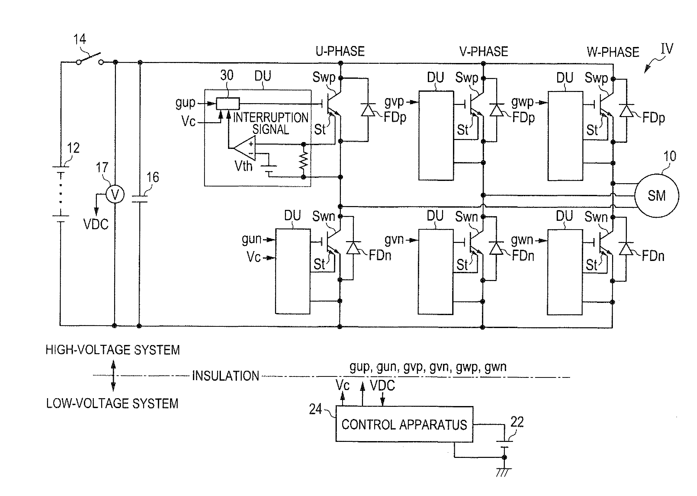
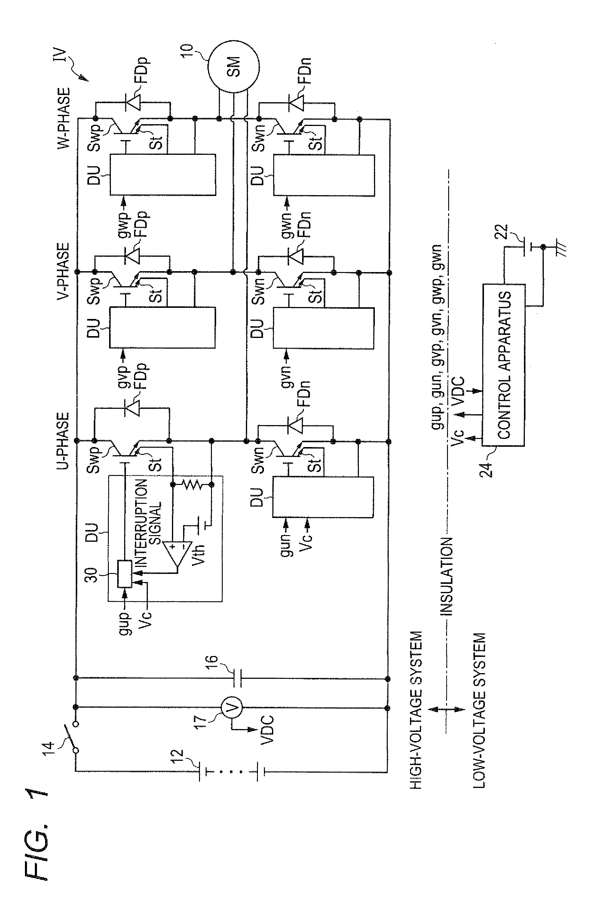
[0031]FIG. 1 is a diagram showing the structure of a power conversion circuit for a hybrid vehicle including a power conversion control apparatus according to a first embodiment of the invention. As shown in FIG. 1, a motor-generator 10 as a vehicle main machine is connected to a high-voltage battery 12 and a capacitor 16 through an inverter IV and a main relay 14. The inverter IV is constituted of three parallel-connected pairs of series connections each including a high-side power switching element Swp and a low-side power switching element SWn. The connection node between the high-side power switching element Swp and the low-side power switching element Swn of each series connection is connected to a corresponding one of the respective phases of the motor-generator 10.

[0032]The input terminals (collector and emitter) of each of the high-side power switching elements Swp are respectively connected to the cathode and anode of a high-side freewheel diode FDp. The input terminals (co...

second embodiment

[0054]Next, a second embodiment of the invention is described with particular emphasis on the difference with the first embodiment.

[0055]FIG. 6 is a time chart explaining the discharge process performed in this embodiment. The sections (a) to (d) of FIG. 6 respectively correspond to the sections (a) to (d) of FIG. 3.

[0056]As shown in FIG. 6, in this embodiment, the low-side power switching element Swn of the U-phase is turned and off multiple times while the power switching element Swp of the U-phase is kept on during the period of the discharge process. Accordingly, a period in which both the high-side power switching element Swp and the low-side power switching element Swn are on occurs multiple times during one period of the discharge process. This makes it possible to prevent the high-side power switching element Swp and the low-side power switching element Swn from being overheated during the discharge process, because no current flows through the high-side power switching elem...

third embodiment

[0060]Next, a third embodiment of the invention is described with particular emphasis on the difference with the second embodiment.

[0061]FIG. 7 is a time chart explaining the discharge process performed in this embodiment. The sections (a) to (d) of FIG. 7 respectively correspond to the sections (a) to (d) of FIG. 3.

[0062]In this embodiment, the on time of the low-side power switching element Swn (the period of time during which the low-side power switching element Swn is on) is increased as the voltage of the capacitor 16 decreases. This is in view of the fact that the heat emitted from the power switching element Sw depends on the discharge energy of the capacitor 16, and the discharge energy is proportional to the product of the voltage and the current of the capacitor 16. The discharge energy decreases as the voltage of the capacitor 16 decreases. Hence, since the heat emitted from the power switching element Sw decreases as the voltage of the capacitor 16 decreases, the tempera...


PUM


Abstract

The power conversion control apparatus is for controlling a power conversion circuit in which a plurality of pairs each including a high-side switching element and a low-side switching element connected in series to each other are connected in parallel to a capacitor, and an external battery is connected to the capacitor through a relay. To discharge the capacitor, the power conversion control apparatus turns on both the high-side and low-side switching elements of at least one of the pairs to make a short circuit between both electrodes of the capacitor on condition that the relay is open.

Description

[0001]This application claims priority to Japanese Patent Application No. 2009-233534 filed on Oct. 7, 2009, the entire contents of which are hereby incorporated by reference.BACKGROUND OF THE INVENTION[0002]1. Field of the Invention[0003]The present invention relates to a power conversion control apparatus for a power conversion circuit in which a plurality of pairs each including a high-side switching element and a low-side switching element connected in series to each other are connected in parallel to a power storage means.[0004]2. Description of Related Art[0005]As described, for example, in Japanese Patent No. 3289567, some of such power conversion control apparatuses are configured to perform discharge control to discharge a storage means (capacitor, for example) connected between a pair of input terminals of an inverter whose output terminals are connected to a motor. The control apparatus described in this patent document performs the discharge control to discharge the char...

Claims


Application Information

Patent Timeline
IPC IPC(8): G05F1/573B60L3/00H02M1/08H02M7/48H02P21/36H02P23/00
CPCH02M1/36H02M2001/322H02M7/53871B60L3/04H02M1/322
Inventor FUKUTA, JUNICHIMAEBARA, TSUNEOSHINDO, YUSUKE
Owner DENSO CORP
Why Eureka
Try Eureka