Supercharge Your Innovation With Domain-Expert AI Agents!

Image processing device, image processing method, and program

Inactive Publication Date: 2011-04-07
TECHNODREAM21
View PDF7 Cites 58 Cited by
  • Summary
  • Abstract
  • Description
  • Claims
  • Application Information

AI Technical Summary

Benefits of technology

[0046]In our invention, by using a simple grid pattern consisting of a number of lines which can be distinguished only vertical or horizontal line, 3D reconstruction are achieved by using intersection points of those lines as feature points. By using such feature points, since relationship between feature points are obtained from connectivity of vertical and horizontal lines, 3D shape which are consistent under intersection of vertical and horizontal lines can be reconstructed as solution set of parameters by applying the shape from coplanarity constraint. In addition, a degree of freedom is one when grid pattern is known, and thus, it can be determined quickly by one dimensional search. Therefore, 3D shape of dynamic scene or moving objects can be densely reconstructed.
[0047]In addition, it has the advantages of the shape not necessarily needing to be globally smooth as long as the local connectivity of the grid points can be extracted and thus allows the shape to be restored even when there are abrupt changes in depth due to an occlusion or in color due to texture. Moreover, since only a discrimination of vertical and horizontal line is required for reconstruction, there remain only a small problem on image processing.

Problems solved by technology

In addition, the design of high-speed synchronization system is also an issue.
Because of the complex patterns, they often require assumptions of smooth surface or reflectance, and the image processing tends to be difficult and to be low resolution.
If the assumptions do not hold, the decoding process of the patterns may be easily affected and leads to unstable reconstruction.
However, in case of a number of feature point is large or there are several feature points on a epipolar line because of a condition of arrangement of feature points, correspondences cannot be uniquely determined.

Method used


Image

  • Image processing device, image processing method, and program
  • Image processing device, image processing method, and program
  • Image processing device, image processing method, and program

Examples


first embodiment

Configuration of the Image Processing Apparatus

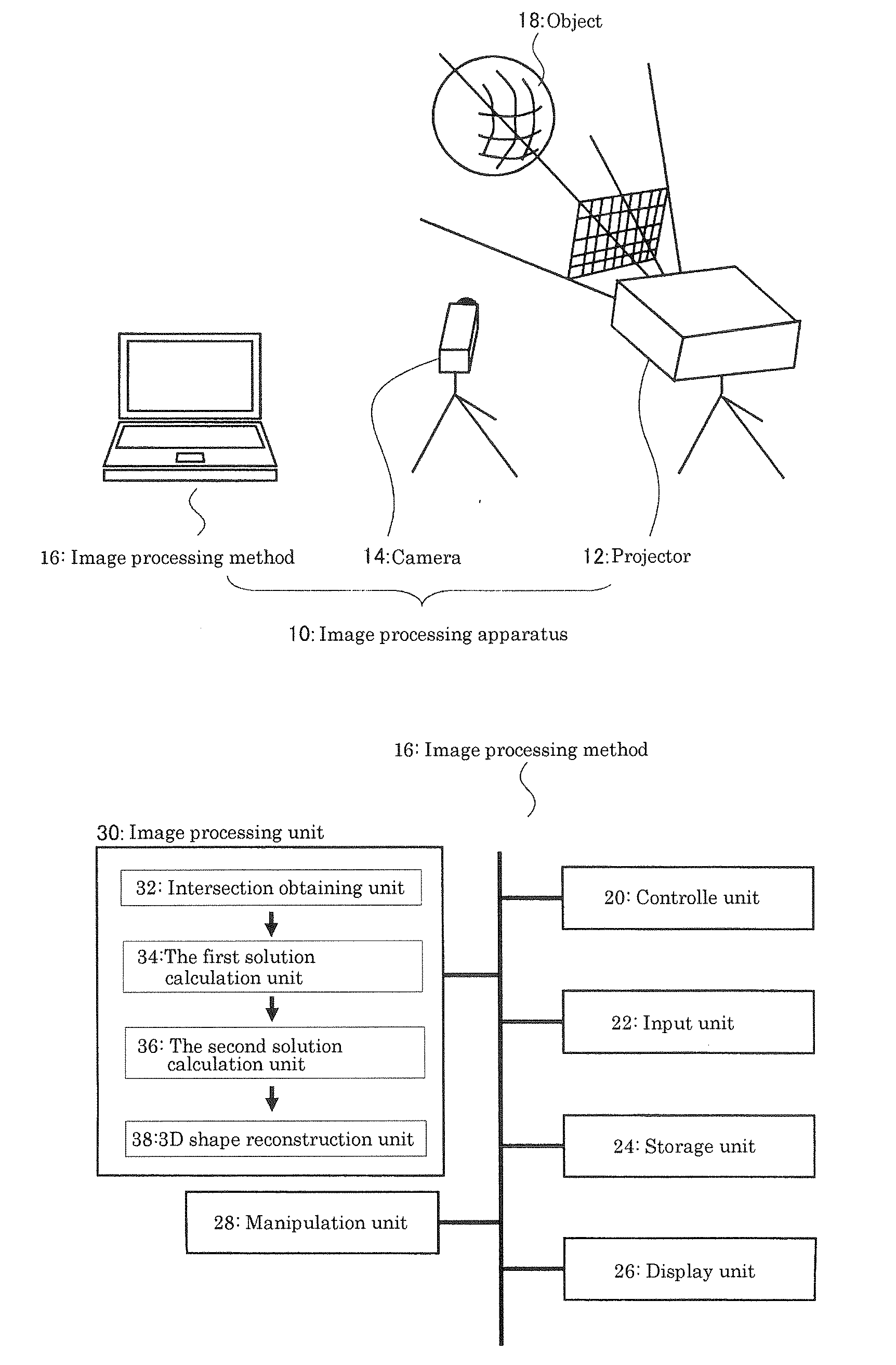
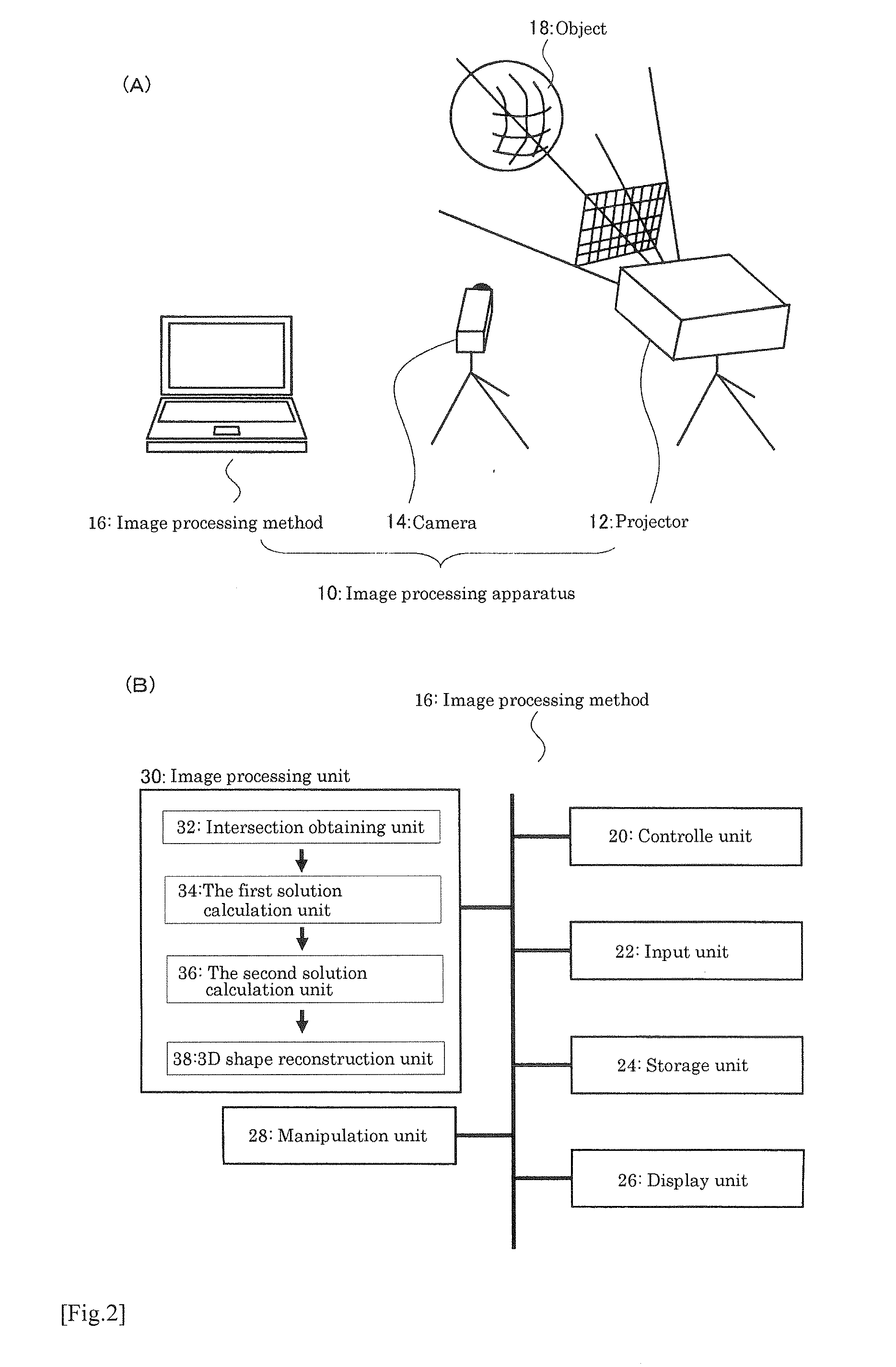
[0077]Configuration of the image processing apparatus regarding to the embodiment of the present invention will now be explained referring to FIG. 1.

[0078]FIG. 1(A) is an example of configuration of the image processing unit 10 and FIG. 1(B) shows a configuration of the image processing method 16

[0079]Referring to FIG. 1(A), the image processing apparatus 10 according to the embodiment mainly includes projector 12 for light projection method, camera 14 for image capturing method and, for example, a personal computer for the image processing method 16.

[0080]Projector 12 has a function to project a light with predetermined pattern to a target object 18 and as for an actual device, for example, video projector can be considered. It is also possible to configure or align line-laser projectors as for an actual devise. Otherwise, using prism or beam-splitter to split laser light source into multiple directions is also possible. Projector 12...

second embodiment

Image Processing Method

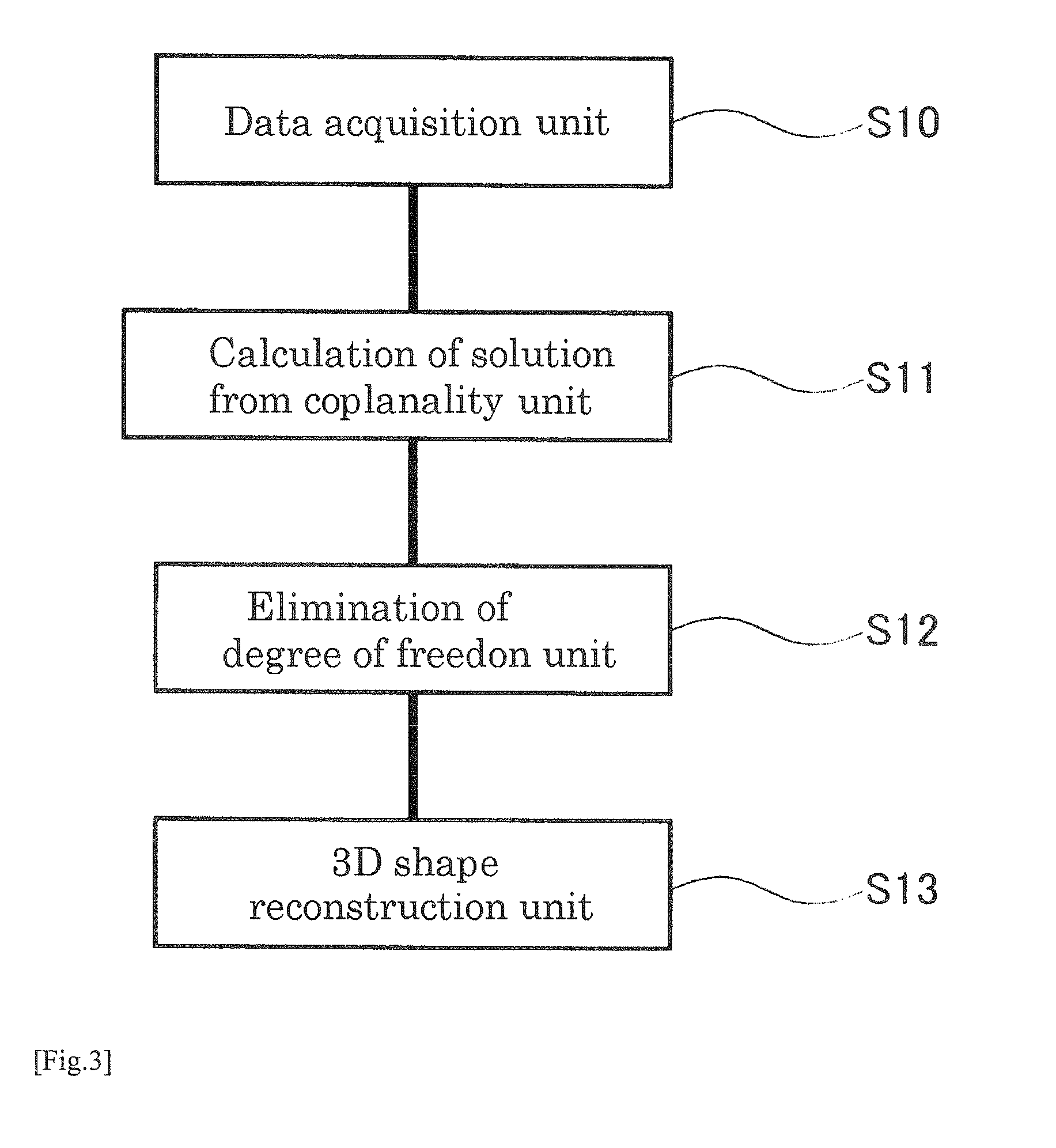
[0096]Before an explanation of the image processing method, planes that are configured by a pattern projected from projector is defined.

[0097]Referring to FIG. 3, a line pattern that is projected from projector 12 defines a plane in a 3D space. In other words, a straight pattern projected by the projector sweeps a plane in 3D space. Planes defined by a vertical pattern and a horizontal pattern are respectively referred to as a vertical pattern plane (VPP) and a horizontal pattern plane (HPP). The projector is assumed to have been calibrated. That is, all parameters for the VPPs and HPPs in 3D space are known (Hereafter, all the parameters and 3D positions for planes, lines and points are represented in the camera coordinate system.). A VPP and a HPP with known parameters are referred to as a calibrated VPP (CVPP) and a calibrated HPP (CHPP). In addition, all CVPPs are assumed to contain the same line (such a set of planes is also known as a pencil of planes)....

third embodiment

of the Present Invention

Positional Relationship Between the Camera and the Projector

[0130]One can improve the precision of the measurement by precisely calibrating the positional relationship between the camera and the projector before the measurement. One method to do that is calibrating parameters using calibration objects. On the other hand, processing calibration before measurement can be a burden. Thus, at the measurement process, processing a self-calibration by projecting a certain set of patterns onto static objects can be useful. This method is described in, for example, Ryo Furukawa, Hiroshi Kawasaki, “Dense 3D Reconstruction with an Uncalibrated Stereo System using Coded Structured Light,” IEEE Computer Society Conference on Computer Vision and Pattern Recognition (CVPR'05) Workshop on Projector-Camera Systems, p. 107, 2005.


PUM


Abstract

[PROBLEM] Provided are an image processing device, an image processing method, and a program which are capable of high density restoration and which are also strong to image processing.[METHOD FOR SOLUTION] An image processing device (10) mainly consists of a projector (12) serving as a projection means, a camera (14) as a photographing means, and an image processing means (16) consisting of, for example, a personal computer. The image processing means (16) acquires the intersection point between patterns from a photographed image and calculates a first solution including degree of freedom by using the constraint condition of a first tentative plane and a second tentative plane including the intersection point and the constraint condition obtained from the positional relationship between the projector (12) and the camera (14). The degree of freedom is cancelled by primary search, thereby restoring a three-dimensional shape.

Description

FIELD OF INVENTION[0001]The present invention relates to an image processing device, image processing method, and program, especially to an image processing device, image processing method, and program for reconstructing a 3D shape from input 2D image.BACKGROUND OF INVENTION[0002]To measure 3D shapes of dynamic scenes or objects, such as human facial expressions or body motions, speed, density and accuracy of measurement are crucial. Since passive stereo techniques have difficulties in reconstructing textureless surfaces densely and accurately, active 3D measurement techniques, especially those using high-speed structured light systems, have been extensively studied in recent years for capturing dynamic scenes.[0003]Since a structured light system reconstructs 3D shape by projecting single or multiple patterns on a scene by a projector and capturing the scene by a camera, correspondences between feature points of projected pattern and captured scene is required. Many structured ligh...

Claims


Application Information

Patent Timeline
IPC IPC(8): G06K9/00
CPCG01B11/25G06T1/00G06T2207/10028G06T2200/08G06T7/0057G06T7/521
Inventor KAWASAKI, HIROSHIFURUKAWA, RYOSAGAWA, RYUSUKEYAGI, YASUSHI
Owner TECHNODREAM21
Features
  • R&D
  • Intellectual Property
  • Life Sciences
  • Materials
  • Tech Scout
  • Unparalleled Data Quality
  • Higher Quality Content
  • 60% Fewer Hallucinations
Learn More