Method for signalling a precoding in a cooperative beamforming transmission mode

a beamforming transmission mode and beam precoding technology, applied in the field of communication, can solve the problems of large amount of signalling and overhead, difficult to obtain efficient beamforming, lack of flexibility, etc., and achieve the effect of reducing the amount of data required for the second indicator and keeping a certain amount of flexibility

Active Publication Date: 2011-04-07
KONINKLJIJKE PHILIPS NV
View PDF7 Cites 42 Cited by
  • Summary
  • Abstract
  • Description
  • Claims
  • Application Information

AI Technical Summary

Benefits of technology

[0020]As a consequence, the secondary station may signal a single first precoding matrix, indicator and keep a certain amount of flexibility in the choice of precoding for the second precoding matrix. It is also possible for the secondary station to signal information upon the second precoding matrix by means of a second indicator representative of the second precoding matrix. But since the choice of precoding for the second precoding matrix is limited to a subset, the amount of data required for the second indicator is reduced.
[0021]Moreover, in an embodiment of the invention, the second precoding matrix represented by the second indicator is based on the value of the first indicator, so that the amount of data used for transmitting the second indicator is less than the amount of data used for transmitting the first indicator. Indeed, the values of the second precoding matrix are limited in accordance with the value of the first precoding matrix. This thus enables the use of a small or reduced second indicator in terms of data bits, because the possible values of the second indicator is limited to a subset of values. This permits flexibility without requiring too much additional signaling in terms of data bits.

Problems solved by technology

However, reception of such a beamformed transmission may require the communication of this set of complex coefficients between the transmitting station and the receiving station.
This may represent a great amount of signalling and overhead.
Thus, the drawback of this is a lack of flexibility.
Moreover, in case of more than two cooperating cells, it may be difficult to obtain an efficient beamforming.
This means that this causes overhead and still a significant amount of signalling.
Moreover, this may lead for some base stations to a potential power imbalance between the different antennas.
This may thus reduce the total available power to that provided by the remaining on antennas, and this would affect the achievable transmit data rate.

Method used


Image

  • Method for signalling a precoding in a cooperative beamforming transmission mode
  • Method for signalling a precoding in a cooperative beamforming transmission mode
  • Method for signalling a precoding in a cooperative beamforming transmission mode

Examples


first embodiment

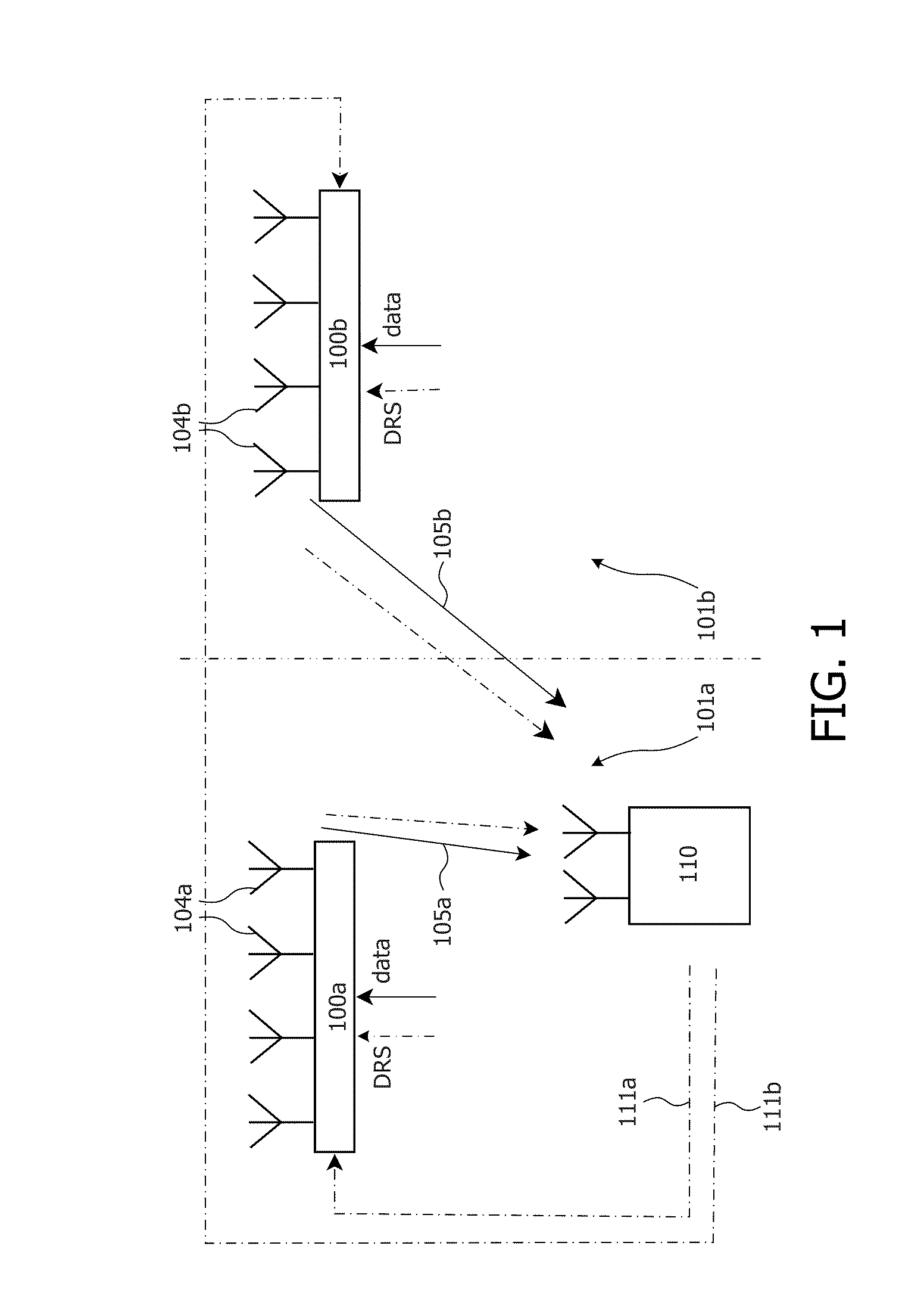
[0049]In accordance with the invention, the secondary station 410, based on the estimation of the channel coefficients, chooses a first preferred precoding matrix in a primary codebook for the cell 401a. The secondary station 410 uses the primary codebook to extract an index that may then be signalled to the first cell 401a by means of a signaling message 411a.

[0050]Furthermore, the secondary station may choose in this first embodiment a preferred precoding matrix for the second cell 401b out of a secondary precoding codebook. This secondary precoding codebook is a limited codebook in the sense that it contains a subset of precoding matrices, namely a limited number of precoding matrices (e.g. 1, 2, or more but less than the total number of the conventional set of available precoding matrices for a conventional secondary codebook). This secondary codebook depends on the value of the preferred precoding matrix for the first cell 401a, or on the value of the index to be signaled in t...

second embodiment

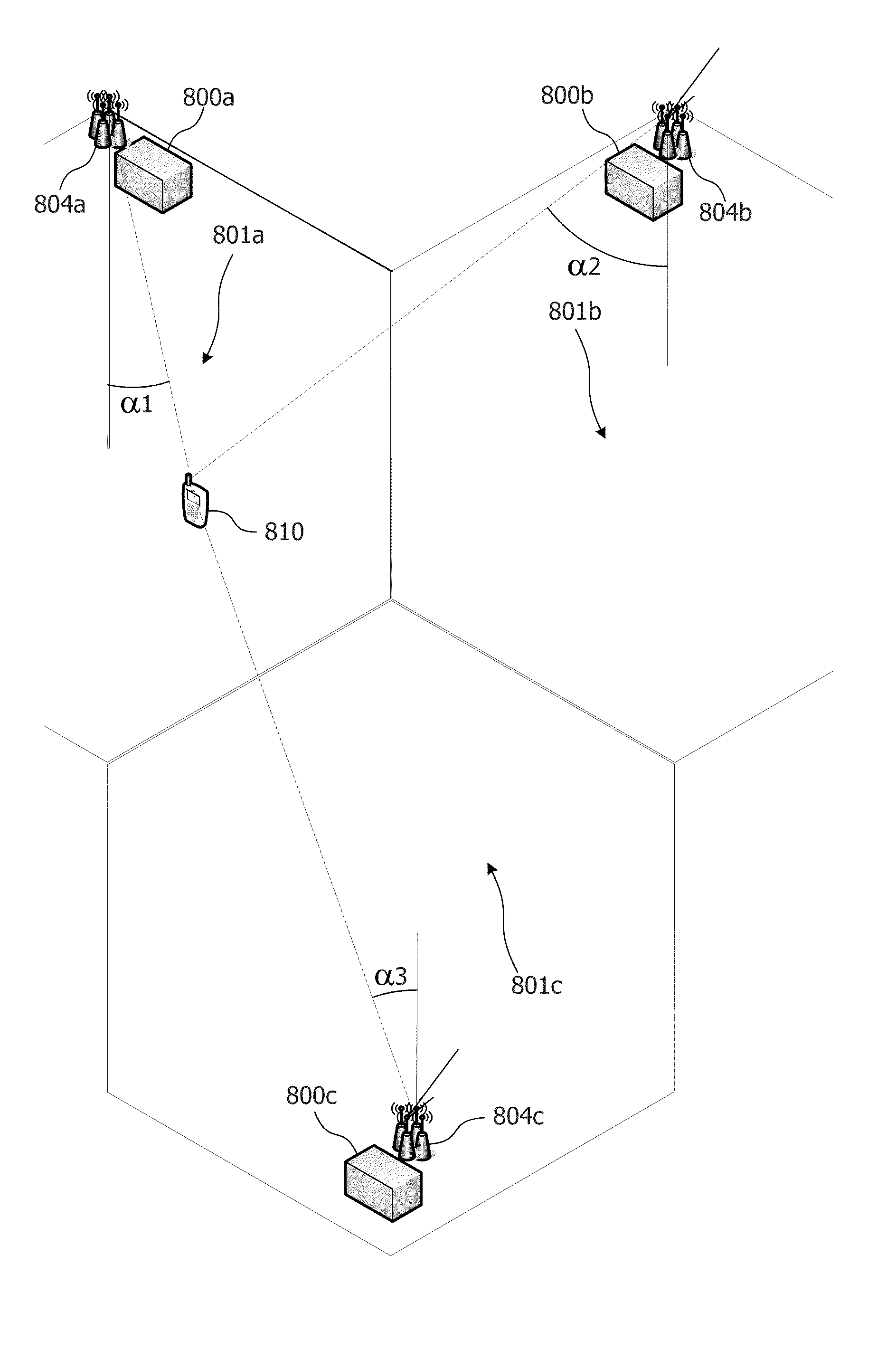
[0078]As a simple example for a better understanding of this second embodiment, let us consider that the cells 601a and 601b (at the same frequency) supported from the same base station site 600 are using uniform linear antenna arrays, with rank 1 transmission in a free-space / line-of-sight channel (LOS). In this case the optimum precoding coefficients depend mainly on the angle α with respect to the antenna array and the codebook can be based on DFT coefficients (i.e. for a given spatial signature, in this case a unique direction with respect to the antenna array, the corresponding precoding coefficients can be obtained via a Discrete Fourier Transform). For a secondary station 610 likely to benefit from CoMP (Cooperative Multipoint Transmission), i.e. in an area served by the two cells, the angles with respect to the two antenna arrays are likely to be similar. Therefore if the secondary station selects optimum precoding coefficients from a codebook for the serving / first cell, the ...

third embodiment

[0127]In accordance with a third embodiment, the precoding scheme may be used as well (or only) by a primary station involved in a cooperative beamforming. In a similar way as the embodiments described previously, the primary station selects a first precoding matrix to signal the precoding applied on the antennas of a first primary station, e.g. itself or another primary station involved in the cooperative beamforming. Then, the precoding of a second primary station may be limited to a subset of precoding matrices (e.g. 1, 2, 3 matrices but less than the whole set of available precoding matrices for the second cell). Then, the precoding of the second cell is chosen in the limited set of precoding matrices and is applied to a primary station involved in the cooperative beamforming. The first primary station may signal the first precoding matrix (by use of a precoding matrix index) and possibly information regarding the second precoding matrix.

[0128]The present invention shall not onl...


PUM


Abstract

The present invention relates to a method for operating a secondary station in a network, the secondary station comprising a transceiver adapted for simultaneously receiving transmissions from a primary station controlling a first cell and at least one primary station controlling a second cell, the method comprising the secondary station
    • (a) selecting a first precoding matrix for the first cell out a primary set of precoding matrices for the first cell,
    • (b) selecting a subset of at least one precoding matrix for the at least one second cell in dependence on the first precoding matrix, out of a set of subsets of precoding matrices for the second cell,
    • (c) selecting a second precoding matrix for the at least one second cell out of the selected subset of precoding matrices for the second cell,
    • (d) transmitting a first indicator representative of the first precoding matrix.

Description

FIELD OF THE INVENTION[0001]The present invention relates to a method of communication in a communication system like a mobile communication system, for example UMTS, LTE or LTE Advanced.[0002]More specifically, the invention relates to a method of communication using beamforming and, in some exemplary embodiments of the invention, cooperative beamforming, i.e. beamforming obtained by using primary station antennas from different cells.BACKGROUND OF THE INVENTION[0003]In a cellular telecommunication system, a plurality of user terminals within a cell communicate with a primary station. With the subsequent generations of cellular systems, the achievable data rate has been keeping increasing. In advanced systems such as UMTS and LTE, multi-antenna transmission / reception techniques variously described as, MIMO, precoding or beamforming are supported for transmissions from a single cell to a mobile terminal. Thanks to the spatial selectivity of the beamforming mode, such transmission mo...

Claims


Application Information

Patent Timeline
Patent Type & Authority Applications(United States)
IPC IPC(8): H04W40/00H04B1/38
CPCH04B7/024H04B7/0617H04B7/0634H04B7/0639H04L25/03891H04B7/0456H04B7/0486H04B7/04H04L5/0035H04B7/0641H04B7/0478H04B7/0658H04L1/06
Inventor MOULSLEY, TIMOTHY JAMESCHIAU, CHOO CHIAP
Owner KONINKLJIJKE PHILIPS NV
Why Eureka
Try Eureka