Paintball loader and paintball Galting gun

a loader and paintball technology, applied in the field of weapons loaders, can solve the problems of reducing the maximum possible cycle speed, limiting the maximum fire rate achievable, and reducing the cycle speed, so as to improve the degree of reliability, prevent paintball breakage, and improve the effect of synchronization

Inactive Publication Date: 2011-04-14
GALINSON RICHARD
View PDF13 Cites 15 Cited by
  • Summary
  • Abstract
  • Description
  • Claims
  • Application Information

AI Technical Summary

Benefits of technology

[0021]The present invention overcomes these problems by providing acceleration and synchronization to prevent paintball breakage.
[0022]One object of this invention to provide a means for improving the degree of reliability achieved within the loader and improving the synchronization between the loader and rotating breech / gun assembly.
[0023]Another object of this invention is to allow a single loader to achieve a much higher rate of fire than prior art has allowed.
[0024]Another object of this invention is to substantially eliminate ball breakage due to timing issues and impact forces.
[0025]A still further object of this invention is to reliably align the paintballs as they transfer from loader to gun to achieve unhindered transfer of balls which are not damaged in the transfer process. This is accomplished through the addition of a set of timing gears.

Problems solved by technology

The first pneumatic projectile launchers used manually actuated reciprocating bolts which have several disadvantages that inherently limit the maximum rate of fire achievable.
Second, any interruption in the flow of projectiles, such as binding in the loading hopper, reduces the cycle speed.
Finally, the bolt must reverse direction during the loading cycle, further reducing the maximum possible cycle speed.
Paintball jams frequently occur within the loader housing during rapid sequential firing of the gun.
These jams prevent the normal gravity delivery of paintballs downwardly through the housing outlet opening, with the result that the paintball stack contained in the feed tube can be totally depleted by several shots of the paintball gun.
The need to dislodge the jammed paintballs is highly undesirable since it interrupts the user's ability to continually fire the gun.
The rate of fire (ROF) of paintball guns has limitations.
Typically, pneumatic bolts can reach their rearmost position, stop and return forward before the ball has time to drop completely into the breech, thereby damaging the fragile ball.
Accordingly, a conventional loader would be unable to feed a rotating gun system at high rates of fire.
The problem is the tendency of paintballs to break due to misalignment of the loader outlet as paintballs are fed into the moving breeches of barrels on a rotating gun assembly.
Prior art loader mechanisms do not reliably chamber the paintball as it is “handed” off from the loader into the firing chamber.
During this part of the operation, control of the timing is not adequate to assure trouble-free operation.
The result is breakage and consequent jamming due to the fragility of the paintballs as the loader feeds individual paintballs into the breeches of successively positioned barrels.
Simply stated, a static, conventional loader cannot be successfully mated to multiple, rotating breeches at high speeds.

Method used


Image

  • Paintball loader and paintball Galting gun
  • Paintball loader and paintball Galting gun
  • Paintball loader and paintball Galting gun

Examples


Embodiment Construction

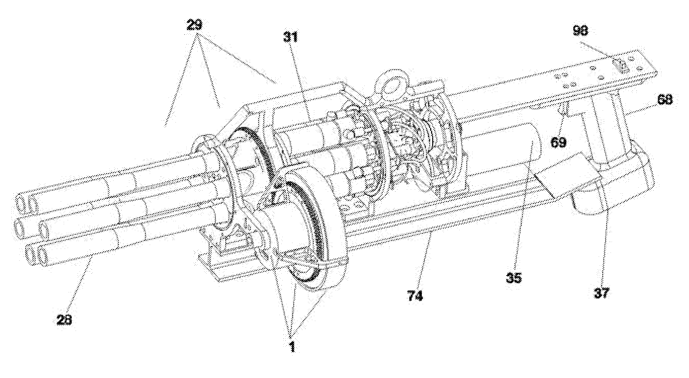
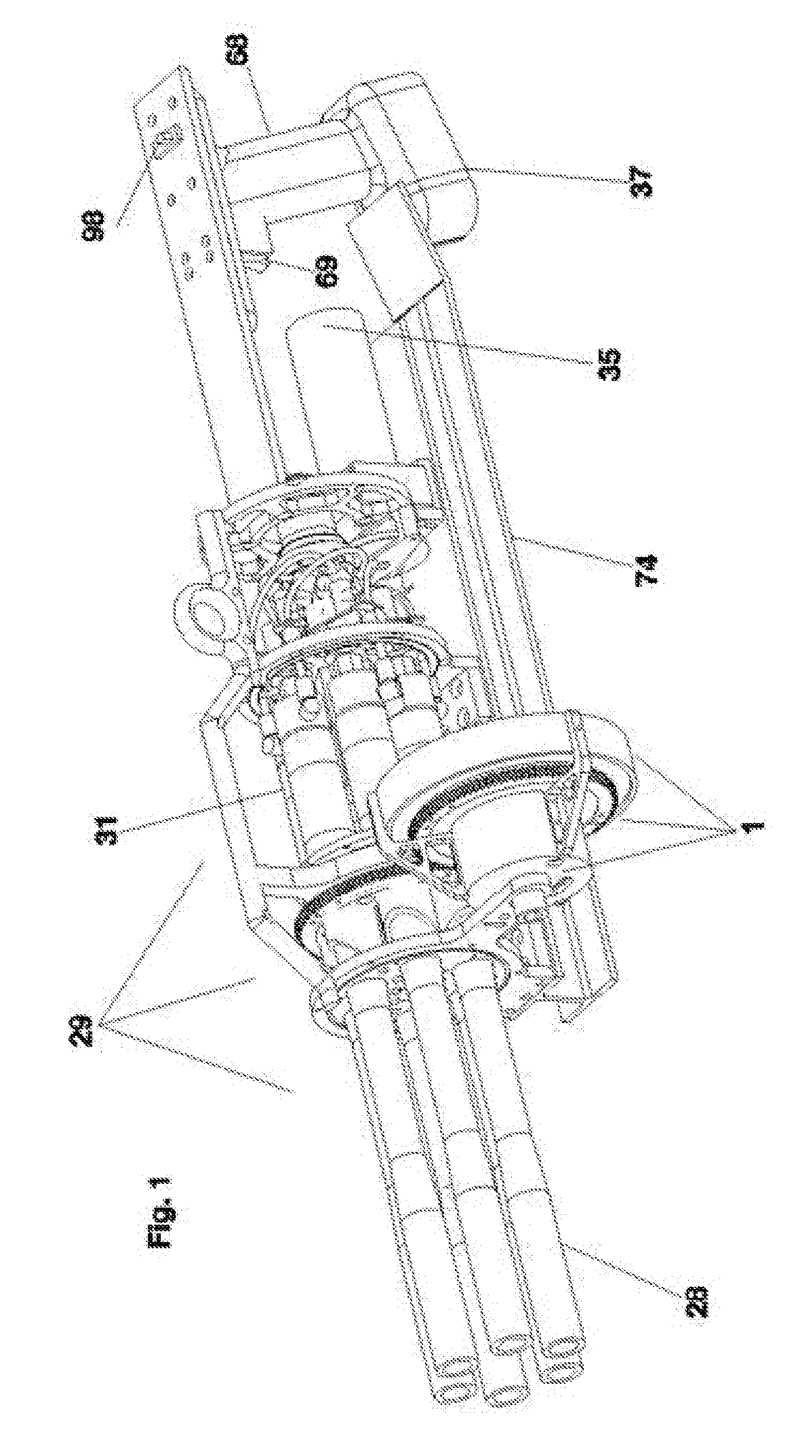
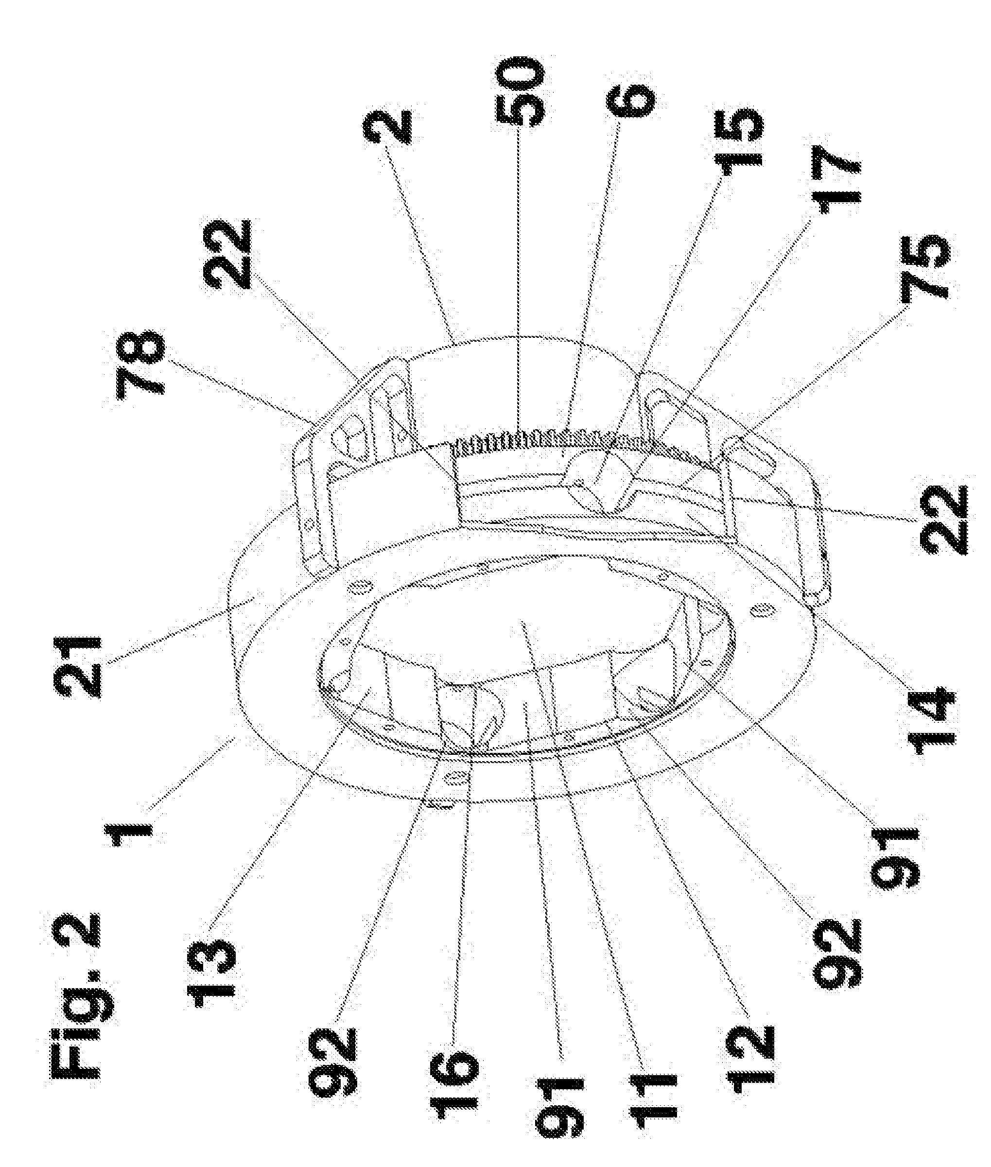
[0054]The inventor has found that successful operation of the gatling projectile gun of the present invention is achieved by a combination of structures that rotates the body of a loader subassembly 6 such that each successive projectile 24 is synchronously positioned with the entrance to a breach opening 26 of a barrel 28 of a set of barrels 30 which comprises a gun subassembly, 29 in rotation about a longitudinal axis 28a of the rotating gun subassembly.

[0055]A preferred embodiment of the present invention is a gatling gun which launches paintballs. Suitable for launching by the gatling gun are projectiles which include, but are not limited to, pepper balls, waterfalls, plastic balls, rubber balls, metal balls or any spherical object that fits inside the diameter of barrels of guns incorporated into the gatling gun. A preferred gun is a standard paintball gun barrel which launches projectiles sufficient in diameter to block the short burst of pressurized gas used to propel it from...


PUM


Abstract

A gatling gun style projectile launcher comprising an assembly of rotating, pressurized-air driven guns. A loader assembly mounted on the gun assembly rotates synchronously through mating of drive gears with the assembly of guns. The loader applies centrifugal force to the paintballs within, urging them into loader tubes positioned in the wall of the loader. Synchronous timing gears align the rotating loader tubes with cognate breech openings in the guns, thereby transferring paintballs into the firing positions from which the paintballs are launched.

Description

[0001]This application claims the benefit of U.S. Non-Provisional Patent Application No. 61 / 270,096, filed Jul. 2, 2009.BACKGROUND OF THE INVENTION[0002]1. Field of the Invention[0003]The present invention relates to a loader for weapons, and, more particularly, to a loader used in conjunction with gatling guns. More specifically, the present invention relates to a paintball loader that is mountable adjacent to a plurality of paintball gun and which sequentially feeds a supply of stored paintballs to the firing chambers of the paintball guns.[0004]2. Description of the Related Art[0005]In the operation of a paintball gun, the player uses a pneumatically powered gun. A variety of gases are used in the art (for example, CO2, Nitrogen, High Pressure Air). Pneumatically powered gun that shoots paintballs are propelled by short bursts of the pressurized gas. Typically, paintballs are gelatin-covered, spherical capsules having a diameter of approximately 11 / 16 inch that contain a colored ...

Claims


Application Information

Patent Timeline
Patent Type & Authority Applications(United States)
IPC IPC(8): F41B11/02
CPCF41B11/54F41A9/36
Inventor GALINSON, RICHARD DAVID
Owner GALINSON RICHARD
Why Eureka
Try Eureka