
Testing of leds

a technology of leds and led components, applied in the field of testing leds, can solve the problems of led failure, light source burnout, and maintenance according to a fixed schedule not being the best solution for lighting fixtures, and achieve the effects of reducing the time needed for reliability tests, increasing implementation speed, and accelerating the effect of aging

Inactive Publication Date: 2011-04-14
NXP BV
View PDF9 Cites 56 Cited by
  • Summary
  • Abstract
  • Description
  • Claims
  • Application Information

AI Technical Summary

Benefits of technology

[0013]This method accelerates the effect of aging in a reproducible way and therefore is able to greatly reduce the time needed for a reliability test. Furthermore, this method allows an increase in speed for implementing feedback on changes in the manufacturing and assembly of LED packages and their impact on the aging effects of the LED.
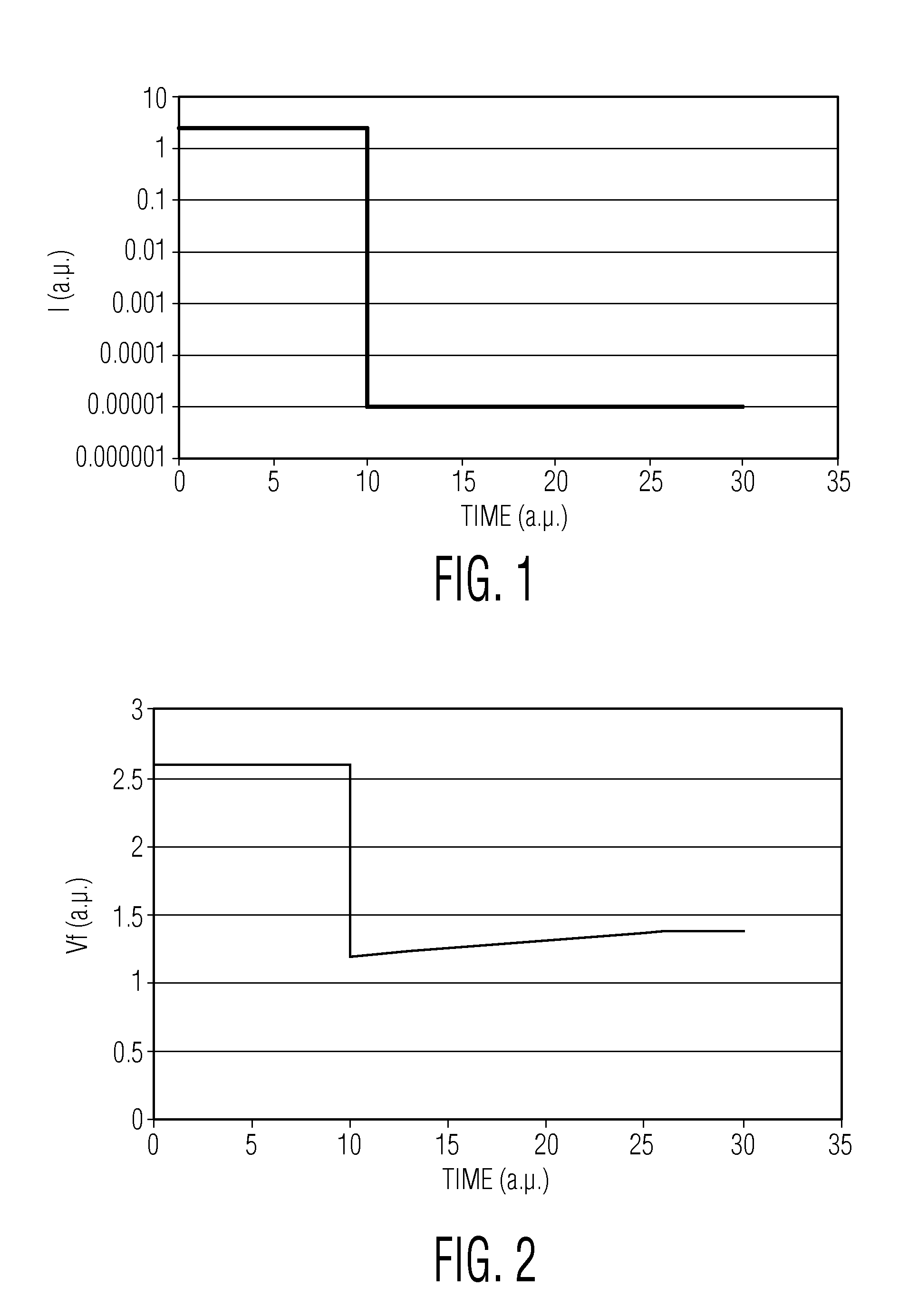
[0024]The current stress pulse preferably has a current value greater than the maximum rated current of the LED. In this way, it provides accelerated ageing of the LED. The current stress pulse is designed to accelerate the ageing process. In general, there are three parameters to accelerate the ageing; the junction temperature, the stress current and the stress duration. The junction temperature is the heat sink temperature raised by an amount which is a function of the stress current and duration. Thus, the junction temperature depends on the stress current pulse, but it can also be controlled to an extent by controlling the heat sink temperature. To accelerate the ageing, conditions can be chosen such as a low heat sink temperature and high stress current, or a low current and high heat sink temperature.

Problems solved by technology

Despite the long LED life time, like many other light sources, the light output from a LED decays over time as a result of an aging process, ultimately leading to LED failure.
It can also happen that a light source is burnt out before its next scheduled maintenance.
Thus, maintenance according to a fixed schedule is not the best solution for lighting fixtures especially for those at difficult to reach places and if safety (or cost) is of concern.
However, because the projected lifetime of LED is in the range of 50000 hrs, it is not practical to observe LED aging behaviour in operating conditions.

Method used


Image

  • Testing of leds
  • Testing of leds
  • Testing of leds

Examples


Embodiment Construction

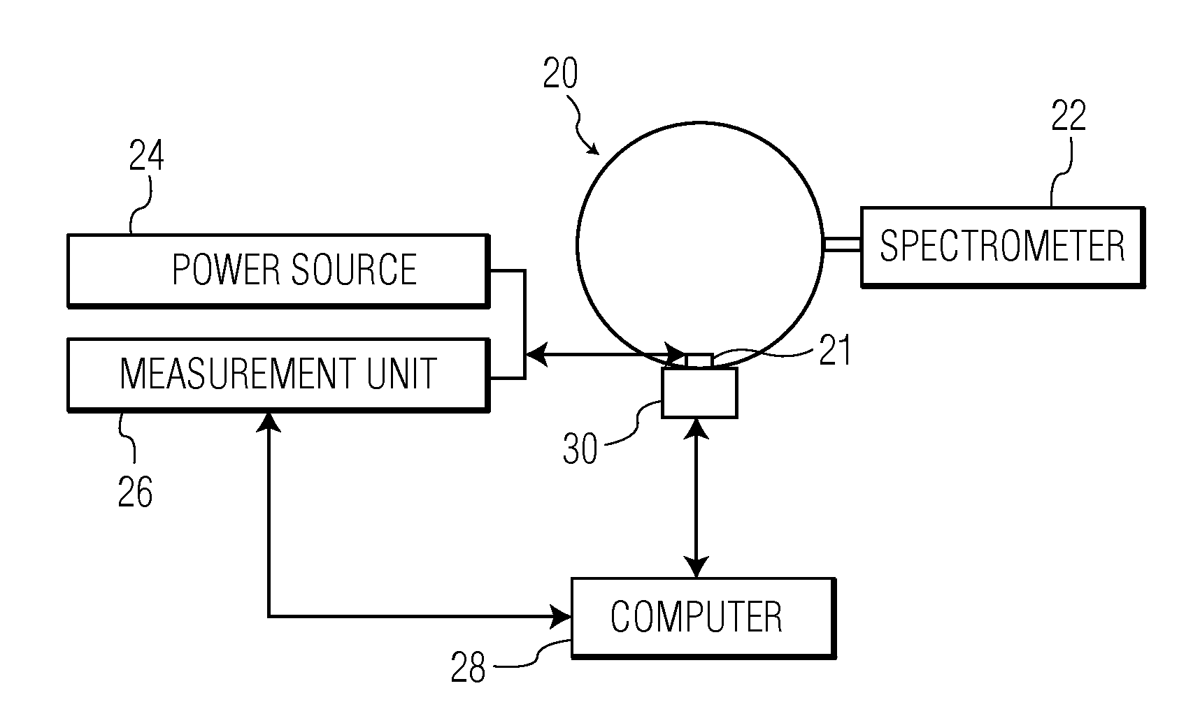
[0051]The invention provides a test method for determining the ageing characteristics of an LED and a test circuit for performing the method.

[0052]The invention makes use of deliberate stressing pulses to induce ageing of the LED, with junction temperature measurement / estimation used to control the application of the stressing pulses. Different approaches for performing junction temperature measurement / estimation of an LED are known, and these will be outlined before describing the invention in further detail.

[0053]During operation, the LED temperature increases and this influences the amount of light output of the LED as well as the dominant wavelength of the output light. Thus, it has previously been recognised that a knowledge of the temperature at the junction of a LED is useful for controlling the LED to have maximum performance.

[0054]Temperature measurement can be used to provide a feedback value for use in controlling the LED driver conditions. Typically, the LED junction tem...


PUM


Abstract

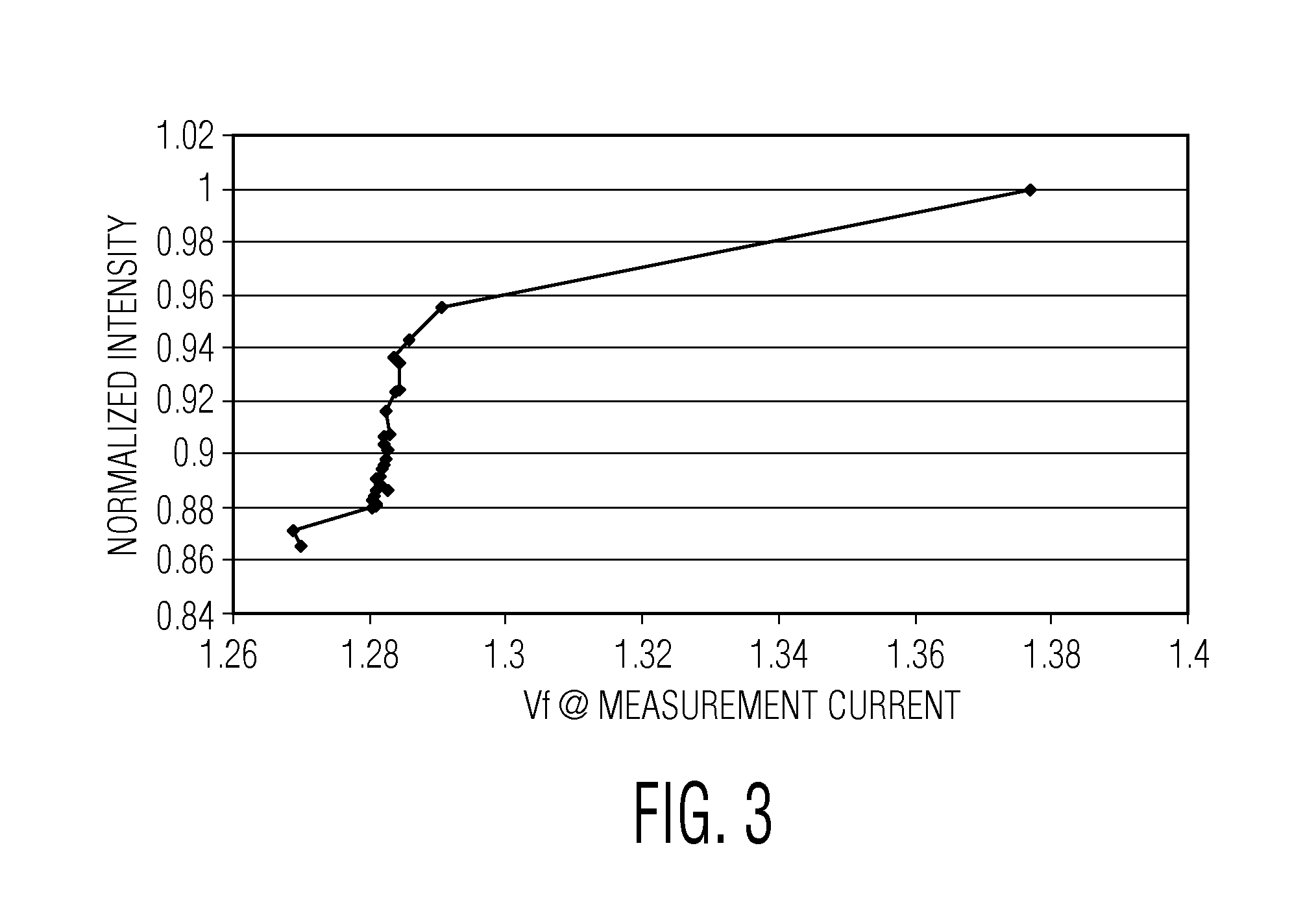
A method of determining the ageing characteristics of an LED comprises applying a current stress pulse to the LED. The LED is monitored to determine when the thermal heating induced by the current stress pulse has been dissipated to a desired level. The operational characteristics of the LED are then measured before applying the next stressing pulse.This method accelerates the effect of aging in a reproducible way and therefore is able to greatly reduce the time needed for a reliability test.

Description

[0001]This application claims the priority of European patent application no. EP09169653.4, filed on Sep. 7, 2009; and EP10153502.9 filed on Feb. 12, 2010 the contents of which are incorporated by reference herein.FIELD OF THE INVENTION[0002]This invention relates to lighting devices using light emitting diodes (LEDs), and particularly to the testing of such devices.BACKGROUND OF THE INVENTION[0003]Lighting using solid-state devices such as LEDs is gaining momentum. The use of LEDs for lighting has several advantages over the use of conventional light sources, including a better light output / dimension ratio and improved power efficiency.[0004]It is reported that the average life time of a LED is approximately 50,000 hours instead of 2000 hours for an incandescent light bulb. As a result, LEDs are the preferred light source in difficult-to-replace lighting fixtures (street lights, traffic signal lights) and / or in fixtures that require higher reliability (automotive lights) for safety...

Claims


Application Information

Patent Timeline
IPC IPC(8): G01R31/00H05B44/00
CPCH05B33/0818G01R31/2642G01R31/2635H05B33/0851H05B45/18H05B45/12
Inventor BANCKEN, PASCALNGUYEN HOANG, VIETSURDEANU, RADU
Owner NXP BV
Learn More