Method and device for operation scheduling for energy storage equipment

a technology for energy storage equipment and operation scheduling, which is applied in adaptive control, process and machine control, instruments, etc., can solve the problems of limited fuel consumption characteristics of equipment existing in the energy system, inability to unconditionally continue power discharge or heat discharge, and inability to achieve the total efficiency initially expected, etc., to improve the overall system the effect of reducing the number of problems and improving the efficiency of the energy system

Inactive Publication Date: 2011-04-14
KK TOSHIBA
View PDF9 Cites 36 Cited by
  • Summary
  • Abstract
  • Description
  • Claims
  • Application Information

AI Technical Summary

Benefits of technology

By implementation of this invention, it is possible to create a supply/demand operation schedule which improves system efficiency for the energy system overall. Further, by means of a method of this invention, even when characteristics of equipment existing in an energy system have complex nonlinearity compared with the prior art, the characteristics can be handled comparatively easily. Also, what is originally a complex problem can be analyzed into partial problems which are comparatively simple and which can be solved independently, so that analysis of results obtained for each partial proble...

Problems solved by technology

However, in actuality the electric power demand state and the heat demand state do not necessarily coincide, and so when supply of either electric power or of heat is matched to demand, the problem occurs that the total efficiency which initially had been expected is not obtained.
When considering operation of an electricity storage equipment or heat storage equipment during a certain term, due to constraints on the capacity of the electricity storage equipment or heat storage equipment, unconditional continuation of power discharge or of heat discharge is not possible, and the need arises to perform power charge or heat charge in a certain time period equal to the amount of reduction in charged power or charged heat due to power discharge or heat discharge in a different time period, to restore the amount of power charge or heat ...

Method used


Image

  • Method and device for operation scheduling for energy storage equipment
  • Method and device for operation scheduling for energy storage equipment
  • Method and device for operation scheduling for energy storage equipment

Examples


first embodiment

1. First Embodiment

{1-1. Summary Configuration and Action}

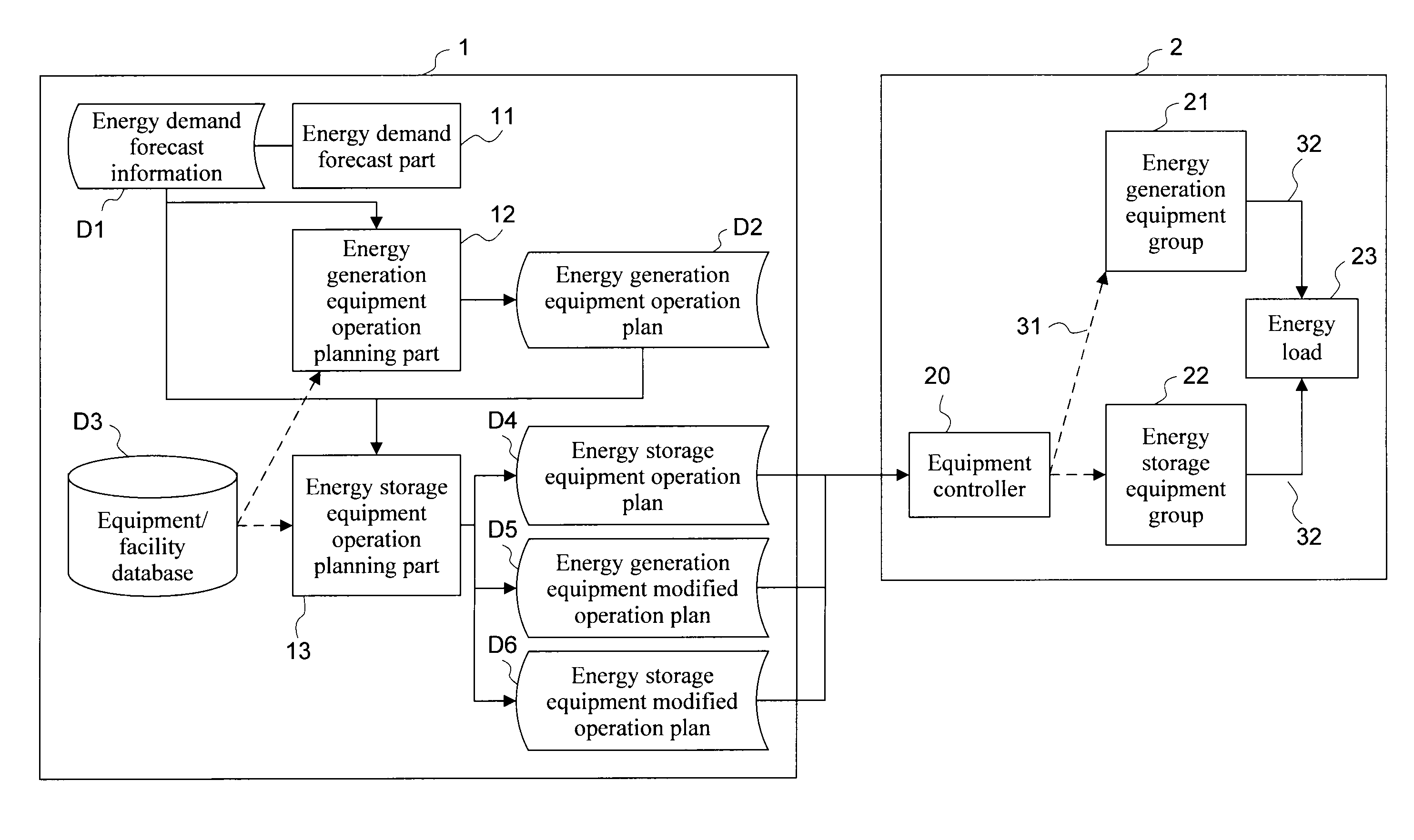
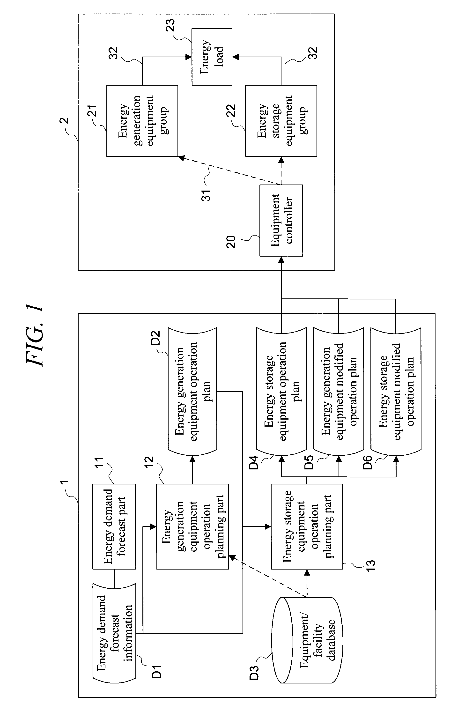
FIG. 1 is a diagram of overall configuration, showing a first embodiment (hereafter in this section, “this embodiment”) of the invention. More specifically, FIG. 1 is a block diagram showing the configuration connecting an energy system operation scheduling device 1 and an energy system 2, and the flow of energy and control information based thereupon.

To summarize, the energy system operation scheduling device 1 creates an energy storage equipment operation schedule D4, an energy generation equipment modified operation schedule D5, and an energy storage equipment modified operation schedule D6, and passes these to an equipment controller 20 of the energy generation system 2.

Upon receiving these schedules, the equipment controller 20 transmits information to control each of the equipment units to an energy generation equipment group 21 composed of power generation facilities and the like, and to an energy storage equipment gro...

second embodiment

{2. Second Embodiment}

Next, a second embodiment (hereafter in this section, “this embodiment”) is explained, using the block diagram of FIG. 4. This embodiment adds an improvement to the specific configuration of the energy storage equipment operation scheduling part 13 of the first embodiment. Otherwise the configuration is similar to that of the first embodiment, and so an explanation is omitted.

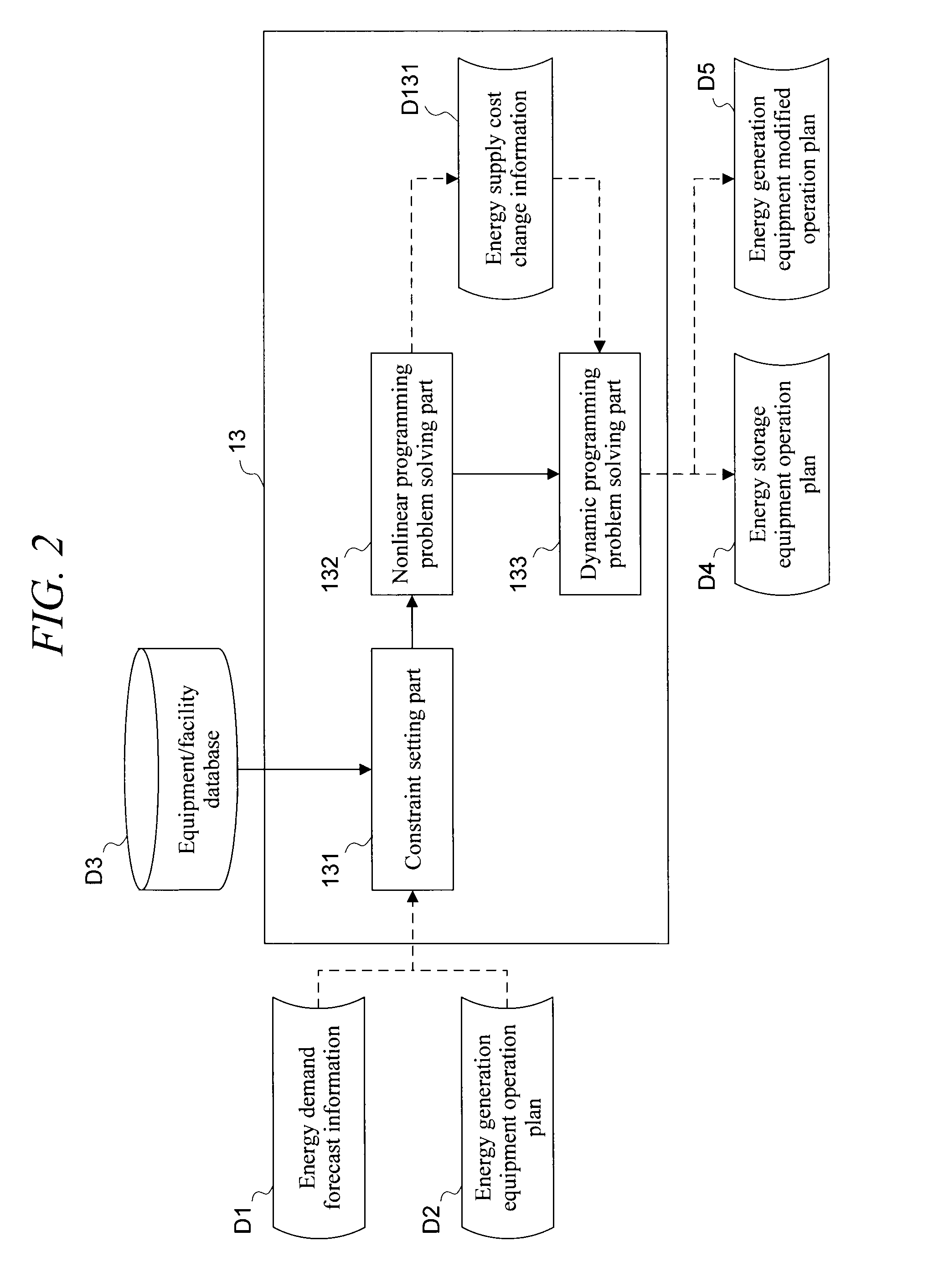
In FIG. 4, the constraint setting part 131 receives three inputs, which are the energy demand forecast information stored in the storage part D1, the energy generation equipment operation schedule stored in the storage part D2, and the equipment / facility information stored in the equipment / facility database D3, and provides problem settings and conditions to nonlinear programming problem solving part 136.

The nonlinear programming problem solving part 136 obtains storage quantity step values of energy storage equipments as an energy storage equipment operation schedule D4. These step values...

third embodiment

{3. Third Embodiment}

Next, a third embodiment (hereafter in this section, “this embodiment”) is explained, using the block diagram of FIG. 6. This embodiment uses, in place of the energy storage equipment operation scheduling part 13 of the first embodiment, energy supply unit-cost calculation part 14, start / stop order calculation part 15, and energy generation equipment start / stop-dependent energy storage equipment operation scheduling part 16. Otherwise this configuration is similar to that of the first embodiment, and so an explanation is omitted.

The energy supply unit-cost calculation part 14 calculates the energy supply unit-cost, and stores this in a storage part D7. The start / stop order calculation part 15 creates a start / stop order based on input of this energy supply unit-cost, and stores the result in a storage part D8.

The energy generation equipment start / stop-dependent energy storage equipment operation scheduling part 16 creates an energy storage equipment operation sch...


PUM


Abstract

In various energy systems which handle a plurality of types of energy, a method and device for operation scheduling for energy storage equipment are provided, which determines optimal operation of an energy storage equipment and improves the efficiency of the energy system overall. An energy storage equipment operation scheduling part 13 creates an energy storage equipment operation schedule, an energy generation equipment modified operation schedule, and an energy storage equipment modified operation schedule, based on three information items, which are the energy demand forecast information stored in a storage part D1, the energy generation equipment operation schedule stored in a storage part D2, and equipment connection information, and sends the created schedules to the equipment controller 20.

Description

TECHNICAL FIELDThis invention relates to a method and device for operation scheduling for energy storage equipment in an energy system having various energy forms.BACKGROUND ARTIn recent years, there has been an increasing number of energy systems which simultaneously handle various energy forms, from the standpoint of global environmental protection and energy conservation.For example, a so-called cogeneration system, in which waste heat is recovered from electric power facilities at the time of electric power generation and is converted into heat conforming to the form of utilization and supplied together with electric power, aims to achieve extremely high total efficiency, nearly double the efficiency when only the generated electric power is used.FIG. 7 is a graph showing the change with time in electric power demand and heat demand in one day in a certain region; the horizontal axis represents time, and the vertical axis represents the electric power load and heat load. As is c...

Claims


Application Information

Patent Timeline
IPC IPC(8): G06F1/26G05B13/02G05B13/04
CPCH02J3/32G05B13/024G06Q10/06H02J3/008Y02B70/3225Y04S20/222Y04S50/10H02J2310/64H02J2203/20H02J3/004H02J3/14Y04S20/00Y02B90/20
Inventor HIRATO, KOTATADA, YOSHIMASA
Owner KK TOSHIBA
Why Eureka
Try Eureka