Solar cell module

a solar cell and module technology, applied in the direction of photovoltaics, electrical apparatus, semiconductor devices, etc., can solve the problems of solar cells being damaged, solar cells being difficult to perform soldering processes using flux, cracks or bowing phenomena,

Inactive Publication Date: 2011-04-21
LG ELECTRONICS INC
View PDF7 Cites 29 Cited by
  • Summary
  • Abstract
  • Description
  • Claims
  • Application Information

AI Technical Summary

Benefits of technology

[0010]When the interconnector and / or the lead wire are / is formed of the lead-free material, it is difficult to perform a soldering process using a flux because of the properties of the lead-free material. Further, because a process temperature rises during a tabbing process, a crack or a bowing phenomenon is generated. Hence, the solar cells may be damaged. An adhesive strength between the elements, on which the tabbing process is performed, for example, between the electrode part and the interconnector or between the interconnector and the lead wire, is therefore reduced.
[0011]However, when the elements, on which the tabbing process is performed, are attached to one another using the adhesive member formed of the conductive adhesive film, the problems generated in the soldering process using the flux may be prevented or addressed.

Problems solved by technology

When the interconnector and / or the lead wire are / is formed of the lead-free material, it is difficult to perform a soldering process using a flux because of the properties of the lead-free material.
Further, because a process temperature rises during a tabbing process, a crack or a bowing phenomenon is generated.
Hence, the solar cells may be damaged.

Method used


Image

  • Solar cell module
  • Solar cell module
  • Solar cell module

Examples


Embodiment Construction

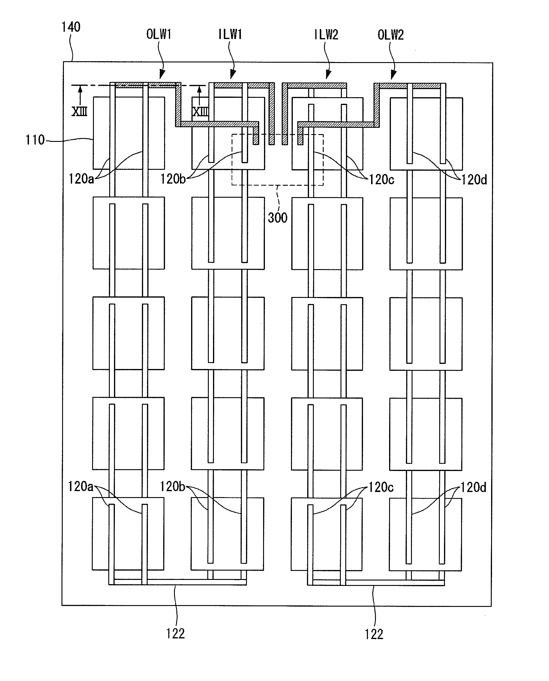
GS. 20 to 22 are plane views of a back surface of a substrate of a solar cell illustrating various configurations of a back electrode;

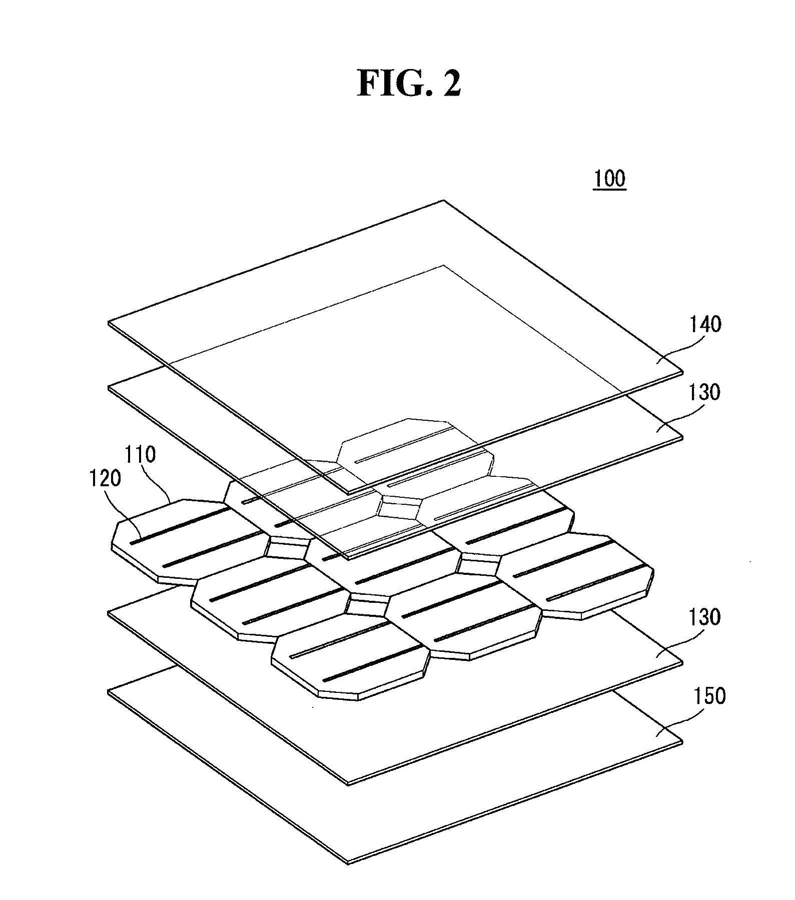
[0030]FIG. 23 is an exploded perspective view illustrating a third example configuration of a solar cell in the solar cell panel shown in FIG. 3;

[0031]FIG. 24 is a plane view of a back surface of a substrate of a solar cell illustrating a configuration of a back electrode;

[0032]FIGS. 25 to 27 are cross-sectional views illustrating various assembly configurations of solar cells of the solar cell panel shown in FIG. 23; and

[0033]FIG. 28 is an exploded perspective view illustrating a fourth example configuration of a solar cell in the solar cell panel shown in FIG. 3.

DETAILED DESCRIPTION OF THE EMBODIMENTS

[0034]The invention will be described more fully hereinafter with reference to the accompanying drawings, in which example embodiments of the invention are shown. This invention may, however, be embodied in many different forms and should not be constru...


PUM


Abstract

A solar cell module is discussed. The solar cell module includes a junction box, a solar cell panel including a plurality of strings of solar cells, each string including a plurality of solar cells that are arranged in a row and are electrically connected to one another, an interconnector for electrically connecting adjacent ones of the plurality of solar cells to one another belonging to at least one of the plurality of strings, a first adhesive member positioned between an electrode part of one of the adjacent solar cells and the interconnector, a lead wire for electrically connecting one end of the interconnector to the junction box, and a second adhesive member positioned between the interconnector and the lead wire. At least one of the interconnector and the lead wire is formed of a lead-free material containing an amount of lead equal to or less than 1,000 ppm.

Description

[0001]This application claims priority to and the benefit of Korean Patent Application No. 10-2010-0079239 filed in the Korean Intellectual Property Office on Aug. 17, 2010, the entire contents of which are incorporated herein by reference.BACKGROUND OF THE INVENTION[0002]1. Field of the Invention[0003]Example embodiments of the invention relate to a solar cell module in which adjacent solar cells are electrically connected to one another using an interconnector.[0004]2. Description of the Related Art[0005]The solar power generation used to convert light energy into electric energy using a photoelectric transformation effect has been widely used as a method for obtaining eco-friendly energy. A solar power generation system using a plurality of solar cell panels has been installed to places, such as houses due to an improvement in a photoelectric transformation efficiency of solar cells.[0006]In a solar cell module, power produced by the solar cells is output to the outside of the so...

Claims


Application Information

Patent Timeline
Patent Type & Authority Applications(United States)
IPC IPC(8): H01L31/05
CPCH01L31/022425H01L31/0504H02S40/34H01L31/0201H01L31/022433Y02E10/50
Inventor HONG, JONGKYOUNGKIM, JONGDAE
Owner LG ELECTRONICS INC
Why Eureka
Try Eureka