
Ion implanter with variable aperture and ion implant method thereof

a technology of ion implants and variable apertures, applied in the field of ion implants, can solve the problems of increasing cost and difficulty, inadequate provision of optimal or popularly required ion beams, and difficulty in adjusting the method of ion beams b>10/b> by applying magnetic fields, etc., and achieves a simple mechanical device, variable aperture, and flexible adjustment

Active Publication Date: 2011-04-21
ADVANCED ION BEAM TECHNOLOGY INC
View PDF6 Cites 12 Cited by
  • Summary
  • Abstract
  • Description
  • Claims
  • Application Information

AI Technical Summary

Benefits of technology

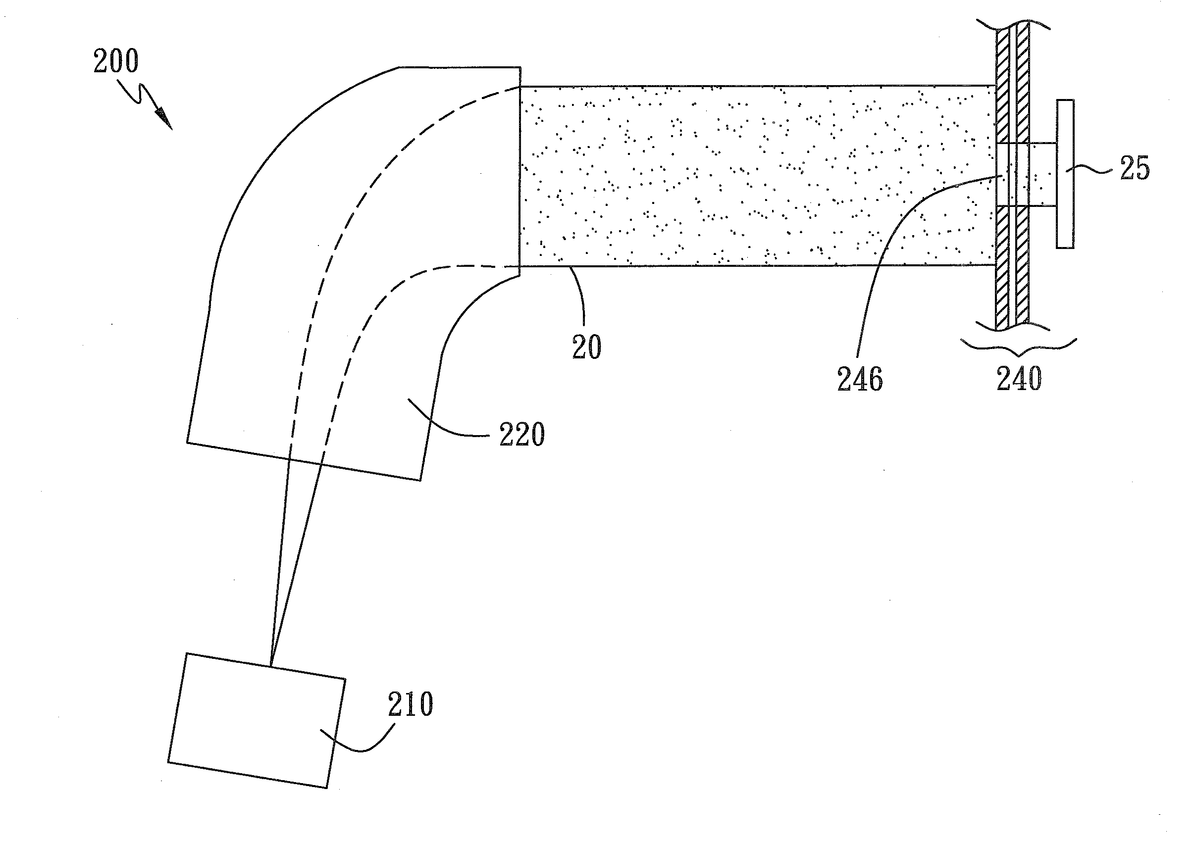
[0013]Note that the aperture assembly with flexible aperture can be located in many positions inside the implanter. Indeed, it only need be located behind the ion source providing the ion beam and before the wafer being implanted. For example, it can be located between the ion source and the mass analyzer; it even can be located inside the mass analyzer. There are two reasons for the position flexibility. First, the existence of the proposed aperture assembly will not affect the operation of other portions of the implanter, because it is a mechanical device and will not affect its neighboring components / functions. Second, the shape and the size of the variable aperture can be flexibly adjusted through a wide range, and the requirement of using different aperture assemblies is significantly less than the requirement of using the conventional plate with fixed aperture.
[0016]The aperture assembly can be a simple mechanical device. For example, each of at least two plates has an opening on its edge and is capable of being respectively moved. Therefore, the variable aperture may be flexibly adjusted by only changing the relative geometric relations among the plates. Accordingly, in comparison with the well-known prior art, the invention can effectively and economically adjust the ion beam to be implanted.

Problems solved by technology

Therefore, an optimal or popularly required ion beam is not properly provided.
However, the method for adjusting the ion beam 10 by applying a magnetic field is difficult and complicated.
However, the cost and the difficulties also are correspondingly increased.
Hence, the potential improvement of ion beam 10 using this method may be limited.
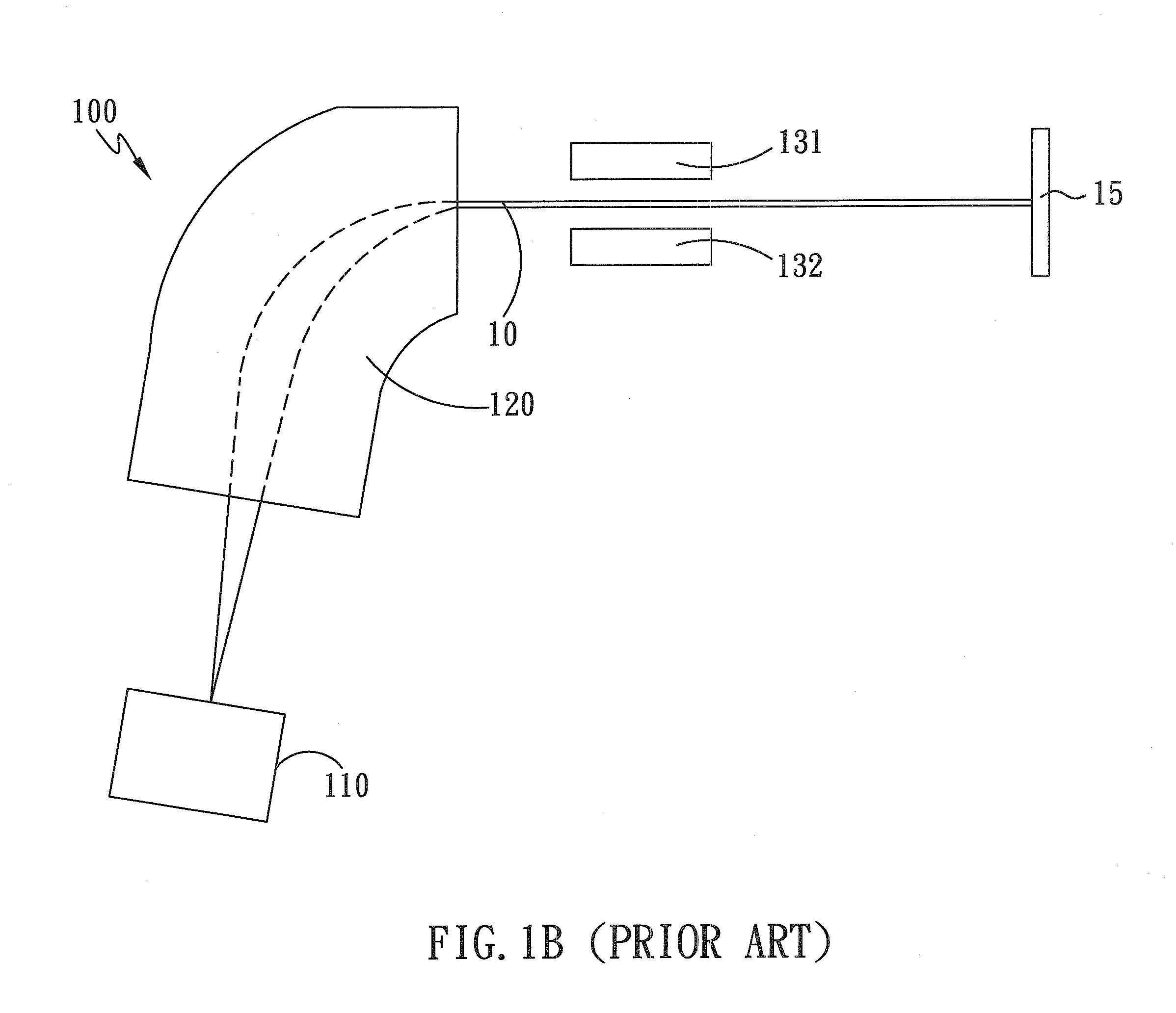
Hence, the associated high cost of numerous plates 133 with different fixed apertures 134 and complex operations for replacing different plates 133 become unavoidable.
Because of disadvantages associated with prior art approaches as mentioned above, there is a need to find a novel ion implanter and a novel method for adjusting the ion beam effectively and economically.

Method used


Image

  • Ion implanter with variable aperture and ion implant method thereof
  • Ion implanter with variable aperture and ion implant method thereof
  • Ion implanter with variable aperture and ion implant method thereof

Examples


Embodiment Construction

[0024]A detailed description of the present invention will be discussed with reference to the following exemplary embodiments, which are not intended to limit the scope of the present invention and can be adapted for other applications. While the drawings are illustrated in detail, it is appreciated that quantities of components are unlimited and may be greater or less than that disclosed.

[0025]FIG. 2A shows a sectional view of an ion implanter 200 in accordance with an embodiment of the present invention. The ion implanter 200 comprises an ion source 210, a mass analyzer 220, and an aperture assembly 240. The ion source 210 is capable of providing an ion beam 20, and the mass analyzer 220 is capable of analyzing the ion beam 20. The aperture assembly 240 has a variable aperture 246 and is capable of adjusting the variable aperture 246 to control size and shape of the ion beam 246, such that the ion beam 20 is shaped before a wafer 25, usually held by a holder (not shown), is implan...


PUM


Abstract

An ion implanter and an ion implant method are disclosed. The ion implanter has an aperture assembly with a variable aperture and is located between an ion source of an ion beam and a holder for holding a wafer. At least one of the size and the shape of the variable aperture is adjustable. The ion beam may be flexibly shaped by the variable aperture, so that the practical implantation on the wafer can be controllably adjusted without modifying an operation of both the ion source and mass analyzer or applying a magnetic field to modify the ion beam. An example of the aperture assembly has two plates, each having an opening formed on its edge such that a variable aperture is formed by a combination of these openings. By respectively moving the plates, the size and the shape of the variable aperture can be changed.

Description

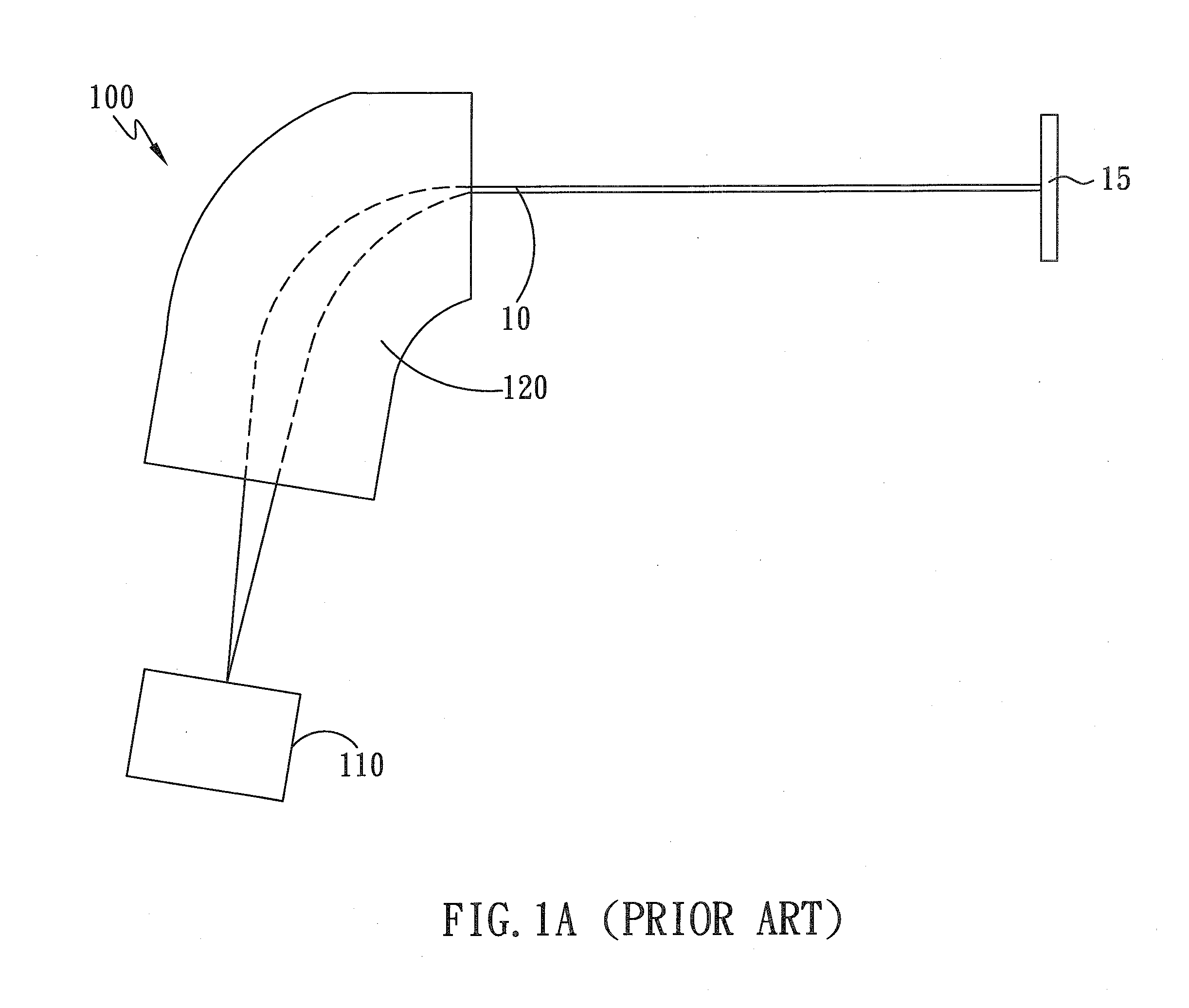
BACKGROUND OF THE INVENTION[0001]1. Field of the Invention[0002]The present invention generally relates to an ion implanter, and more particularly, relates to an ion implanter having a variable aperture capable of flexibly shaping an ion beam before a wafer is implanted.[0003]2. Description of the Prior Art[0004]FIG. 1A is a sectional view for a conventional implanter 100. The conventional implanter 100 has at least an ion source 110, a mass analyzer 120, and a holder (not shown). The ion source 110 is capable of providing an ion beam 10. The mass analyzer 120 is capable of analyzing the ion beam 10 so that the ions with un-desired charge-to-mass ratios are moved away from the ion beam 10. After that, the ion beam 10 with required ions is implanted into the wafer 15 held by the holder.[0005]As usual, the ion beam 10 outputted from the mass analyzer 120 is not as perfect as required. For example, the shape (the cross-sectional shape) of the ion beam 10 may be irregular or the ion bea...

Claims


Application Information

Patent Timeline
Patent Type & Authority Applications(United States)
IPC IPC(8): H01J3/14G21K5/04
CPCH01J37/09H01J2237/0455H01J37/3171
Inventor MCRAY, RICHARD F.
Owner ADVANCED ION BEAM TECHNOLOGY INC
Learn More