Implantable Electrical Stimulator

Active Publication Date: 2011-04-21
MAN & SCI
View PDF46 Cites 182 Cited by
  • Summary
  • Abstract
  • Description
  • Claims
  • Application Information

AI Technical Summary

Benefits of technology

[0009]An aspect of an embodiment of the invention, relates to an implantable stimulator for stimulating muscles and/or nerves, with a dynamically controllable array of electrodes. The array of electrodes is made up from one or more rows and one or more columns of electrodes positioned on a surface that can be placed in contact with a muscle/nerve. Optionally, the stimulator may have multiple arrays, for example one on each side of the stimulator or even multiple ar

Problems solved by technology

This method requires a high level of expertise from the practitioner and may be very time consuming.
Some problems may occur after positioning the stimulator.
One problem is that a rigid stimulator may damage the muscles/nerves or surrounding tissue and lead to complications, fo

Method used


Image

  • Implantable Electrical Stimulator
  • Implantable Electrical Stimulator
  • Implantable Electrical Stimulator

Examples


Embodiment Construction

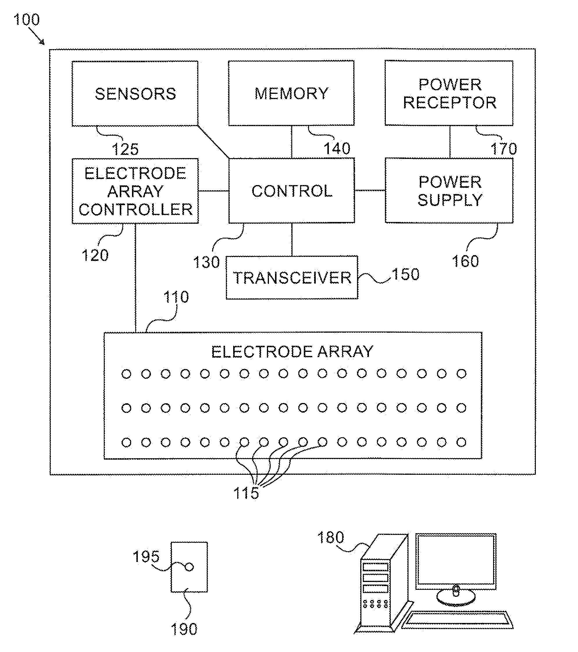
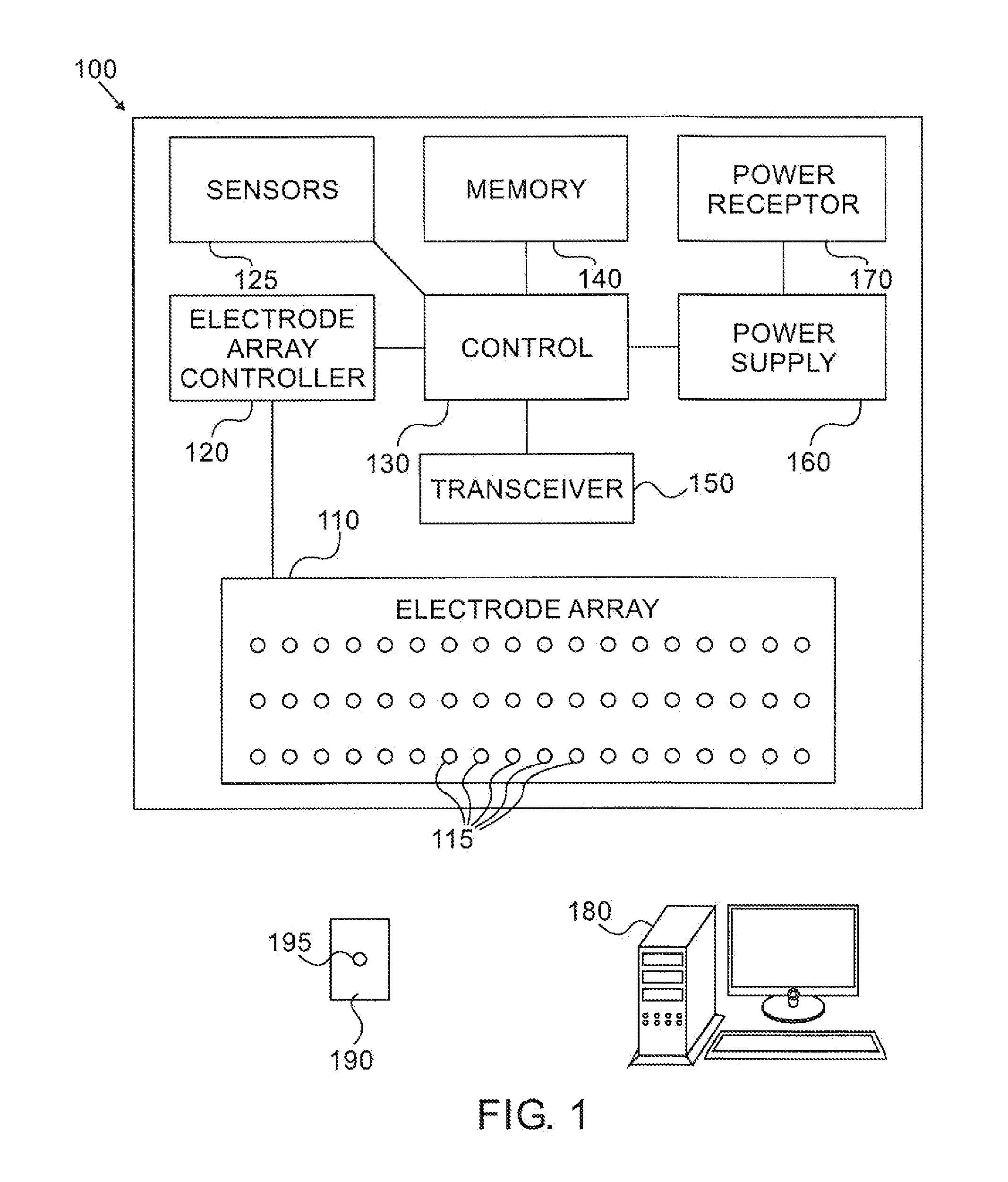
[0067]FIG. 1 is a schematic illustration of a block diagram of an electrical stimulator 100, according to an exemplary embodiment of the invention. In an exemplary embodiment of the invention, stimulator 100 includes an electrode array 110, which is designed to be placed in contact with the contact points of nerves or muscles, or in proximity thereof, so that the electrodes can stimulate the contact points. Optionally, the electrode array is denser than the contact points on the muscle or nerve (e.g. 1-100,000 electrodes per millimeter, or per centimeter) or the array of electrodes occupies an area larger than that of the muscle / nerve contact point, so that each contact point on the muscle or nerve that needs to be stimulated will have one or more electrodes 115 in contact with it. In some embodiments of the present invention, some or all of the electrodes can be placed in proximity with the contact points of nerves or muscles. In the context of the present invention placed, include...


PUM


Abstract

An implantable stimulator for stimulating muscles or nerves, including, an array of electrodes for electrically stimulating muscles or nerves, a controller for controlling the activity of the electrodes, and wherein the controller is adapted to dynamically select the electrodes that are used to participate in stimulating the muscles or nerves.

Description

FIELD OF THE INVENTION[0001]The present invention relates generally to an implantable electrical stimulator and more specifically to an implantable electrical stimulator with a dynamically controlled electrode array.BACKGROUND OF THE INVENTION[0002]Implanting a stimulator to stimulate muscles or nerves is a complex procedure. Generally in the case of nerve stimulation, a special electrode is used, such as a cuff electrode. Generally the electrode is in the form of a wire extending from the stimulator to the nerve. Implantation of the stimulator requires surgical intervention to expose the position for implanting the electrode and stimulator and then requires fine-tuning the placement of the electrode so that accurate contact will be formed between the electrodes of the stimulator and specific contact points along the muscles or nerves.[0003]In the case of muscle stimulators, the electrodes are typically positioned to form contact with the motor end plate of a muscle, also called the...

Claims


Application Information

Patent Timeline
IPC IPC(8): A61N1/08A61N1/36
CPCA61N1/05A61N1/3756A61N1/3601A61N1/0553
Inventor MASHIACH, ADI
Owner MAN & SCI
Why Eureka
Try Eureka