Electric wire with terminal connector and method of manufacturing electric wire with terminal connector

a technology of terminal connector and electric wire, which is applied in the direction of electrically conductive connections, cable junctions, and connection formation by deformation, etc., can solve the problems of insufficient electrical connection of wires to each other, and achieve the effect of reducing the electric resistance between the electric wire and the terminal connector

Inactive Publication Date: 2011-04-28
AUTONETWORKS TECH LTD +2
View PDF4 Cites 51 Cited by
  • Summary
  • Abstract
  • Description
  • Claims
  • Application Information

AI Technical Summary

Benefits of technology

[0004]According to the above structure, the contact between an outer peripheral surface of the core wire and an inner surface of the crimping portion electrically connects the core wire and the crimping portion. If a layer having a relatively high electric resistance such as an oxide layer is formed on a surface of each wire forming the core wire, the wires may not be electrically connected to each other sufficiently due to the layer formed on each wire. In such a case, only the wires that are located at a radial outer portion of the core wire and connected to the inner surface of the crimping portion contribute to the electric connection between the core wire and the crimping portion. Accordingly, the wires that are located at a radial inner portion of the core wire may not contribute to the electric connection between the core wire and the crimping portion. This may increase an electric resistance between the electric wire and the terminal connector.
[0005]The present invention has been completed in view of the circumstances described above. It is an object of the present invention to provide an electric wire with terminal connector that decreases an electric resistance between an electric wire and a terminal connector and also provide a method of manufacturing such an electric wire with terminal connector.
[0009]If the crimping portion is crimped onto the core wire of the wires having the roughed portion, the wires rub against each other by the application of force from the crimping portion. Then, the roughed portion formed on the surfaces of the wires rub against each other, and this makes the layer such as the oxide layer formed on the surfaces of the wires to be removed. Then, the surfaces of the wires emerge. The exposed emerging surfaces are contacted to each other and the wires are electrically connected to each other. Thus, the wires located at a radial inner portion of the core wire contribute to the electric connection between the electric wire and the terminal connector. This decreases an electric resistance between the electric wire and the terminal connector.
[0010]As described above, according to the present invention, an electric resistance between the electric wire and the terminal connector is decreased.

Problems solved by technology

If a layer having a relatively high electric resistance such as an oxide layer is formed on a surface of each wire forming the core wire, the wires may not be electrically connected to each other sufficiently due to the layer formed on each wire.

Method used


Image

  • Electric wire with terminal connector and method of manufacturing electric wire with terminal connector
  • Electric wire with terminal connector and method of manufacturing electric wire with terminal connector
  • Electric wire with terminal connector and method of manufacturing electric wire with terminal connector

Examples


example 1

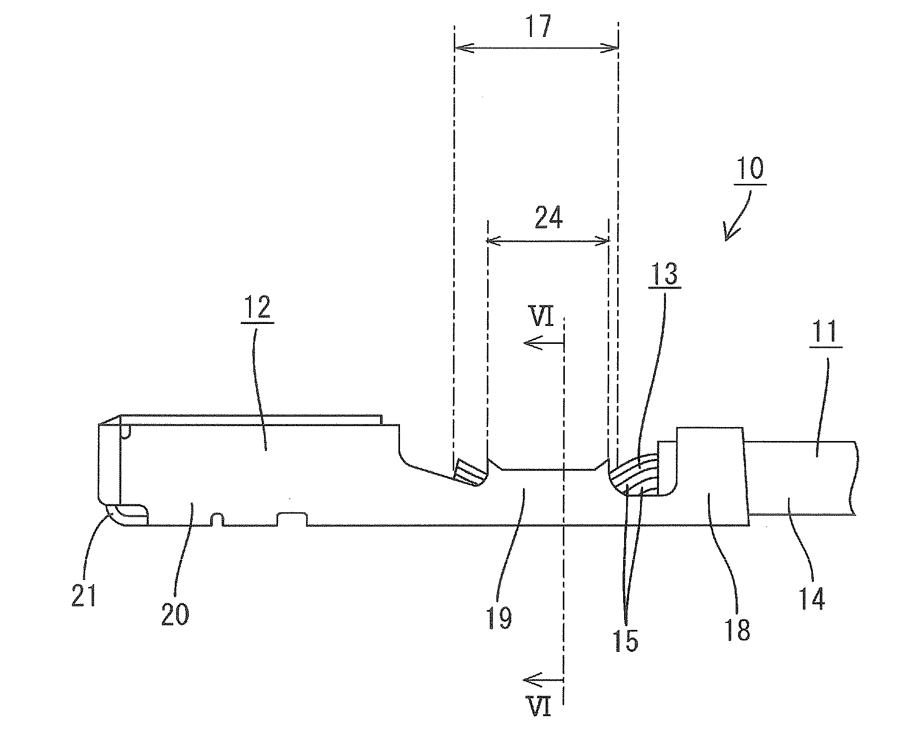
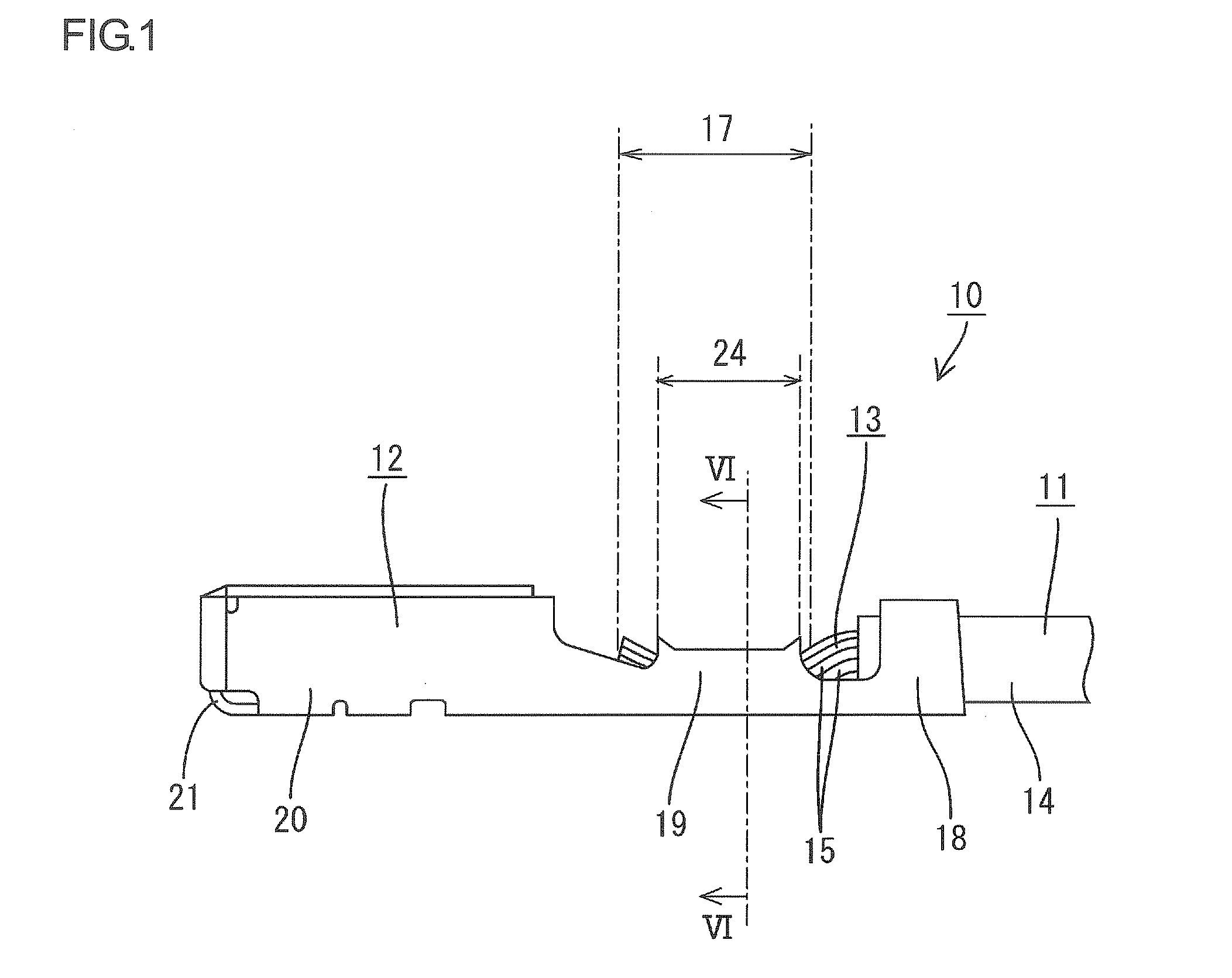
[0075]A metal plate material is pressed into a predetermined shape with a die. Then, the metal plate material that is formed in the predetermined shape is processed to be bent to form the connecting portion 20.

[0076]Thereafter, the wire insulation 14 is removed at the end of the electric wire 11 to expose the core wire 13 therefrom. Then, the core wire 13 is held between the jigs 16, 16 and the ultrasonic vibration is applied to the core wire 13 such that the wires 15 are welded. The condition at this time is that contact pressure of the jigs 16 is 13 bar, frequency is 20 kHz and applied energy is 80 Ws.

[0077]After the welded wires 15 are separated into a plurality of independent wires 15 again, the wire barrel 19 is crimped onto the core wire 13 and thus an electric wire with terminal connector 10 is manufactured.

[0078]As illustrated in FIG. 6, the wire 15 located close to a position P that is close to the radial outward portion of the core wire 13 and the wire 15 located close to ...

example 2

[0080]Another electric wire with terminal connector 10 is manufactured in the same way as EXAMPLE 1 except for the condition that the contact pressure of the jigs 16 is 1 bar and the applied energy is 60 Ws.

[0081]FIGS. 9 and 10 illustrate electron microscope photographs of the surfaces of the wires 15 after the application of ultrasonic vibration. The electron microscope photograph of FIG. 9 is taken at a magnification of 30 times and that of FIG. 10 is taken at a magnification of 4000 times.

example 3

[0082]Another electric wire with terminal connector 10 is manufactured in the same way as EXAMPLE 1 except for the condition that the contact pressure of the jigs 16 is 0.5 bar and the applied energy is 30 Ws.

[0083]FIGS. 11 and 12 illustrate electron microscope photographs of the surfaces of the wires 15 after the application of ultrasonic vibration. The electron microscope photograph of FIG. 11 is taken at a magnification of 30 times and that of FIG. 12 is taken at a magnification of 4000 times.


PUM

PropertyMeasurementUnit
frequencyaaaaaaaaaa
contact pressureaaaaaaaaaa

Abstract

An electric wire with terminal connector including an electric wire having a core wire including a plurality of wires and a female terminal connector including a wire barrel that is crimped onto the core wire exposed from the electric wire, the following steps are executed. The steps include a step of removing wire insulation covering an outer peripheral surface of the core wire to expose the core wire, a step of holding the exposed core wire with jigs provided in a pair and applying ultrasonic vibration to the core wire via the jigs, and a step of crimping the wire barrel so as to surround a part of the core wire to which the ultrasonic vibration is applied.

Description

TECHNICAL FIELD[0001]The present invention relates to an electric wire with terminal connector and a method of manufacturing the electric wire with terminal connector.BACKGROUND ART[0002]Conventionally, an electric wire with terminal connector disclosed in Patent Document 1 is known as an example of such a kind. The electric wire with terminal connector comprises an electric wire that is a core wire 13 including a plurality of wires and a terminal connector that is crimped onto the core wire that is exposed from the electric wire. The terminal connector includes a crimping portion that is crimped onto the core wire so as to surround it. The crimping portion is crimped onto the core wire so as to surround it, and this electrically connects the electric wire and the terminal connector.[0003][Patent Document 1] Japanese Unexamined Patent Publication No. 9-7647DISCLOSURE OF THE INVENTION[0004]According to the above structure, the contact between an outer peripheral surface of the core w...

Claims


Application Information

Patent Timeline
Patent Type & Authority Applications(United States)
IPC IPC(8): H01R4/18H01R43/00
CPCH01R4/625Y10T29/49174H01R43/05H01R43/0207H01R4/029H01R4/185
Inventor OTSUKA, TAKUJIHIRAI, HIROKIONO, JUNICHITANAKA, TETSUJISHIMODA, HIROKIITO, AKIRAHIGUCHI, HISASHIHAGI, MASAHIRO
Owner AUTONETWORKS TECH LTD
Why Eureka
Try Eureka