Coupling

a technology of coupling and sealing surface, applied in the direction of sleeve/socket joint, non-disconnectible pipe-joint, joints with sealing surfaces, etc., can solve the problems of reducing the corrosion resistance of surfaces, adding to the assembly time, and leaking paths with these fittings

Inactive Publication Date: 2011-04-28
NICHOLSON SPENCER
View PDF4 Cites 6 Cited by
  • Summary
  • Abstract
  • Description
  • Claims
  • Application Information

AI Technical Summary

Benefits of technology

[0018]The coupling requires only two parts reducing manufacturing costs and making assembly straightforward. Furthermore as the body, which has one or more interior annular protuberances which extend into the bore prior to use, is deformed such that the one or more annular protuberances provided thereon are forced into engagement with the tube or like, it has been found that a particularly robust seal is provided. The tube or the like is retained in the inner body providing considerable resistance to being axially withdrawn.
[0020]As the inner body upon which the annular protuberances are provided is deformed, the annular protuberances can undergo a larger radial displacement than conventional ferrules. This larger radial displacement enables higher compressive loads to be placed on the tube or the like providing better seals and grip and the coupling can be used with tubes or the like with larger dimensional tolerances than conventional ferrule couplings. Furthermore, the large radial displacement of the annular protuberances compresses the cross-section of the tube or the like where they engage which splays the tube or the like on either side. The splaying of the tube or the like on either side enhances the resistance to withdrawal of the tube or the like from the coupling. The larger radial displacement of the annular protuberances enables the coupling to be used with tube or the like which has not been specially prepared and which may have scratches reducing preparation time for the tube and thus costs. Furthermore, unlike conventional ferrule fittings, the tube or the like does not need to abut against a stop within the coupling as the protuberances provide such a good seal. This overcomes the need for the end of the tube or the like to be cut precisely square, further reducing preparation time and costs. The larger radial displacement of this coupling compared to conventional ferrule fittings provides larger forces such that the material of the engaging protuberances does not need to be specially hardened unlike conventional ferrule fittings. However, the protuberances could, if desired, be hardened for advanced performance. The larger radial displacement of this coupling also ensures that the protuberances engage all points around the circumference of a tube or the like, even when its cross-section is not precisely round. For example a tube or the like with a slightly oval cross-section will be pushed back into shape and a better connection will be made compared to conventional fittings.
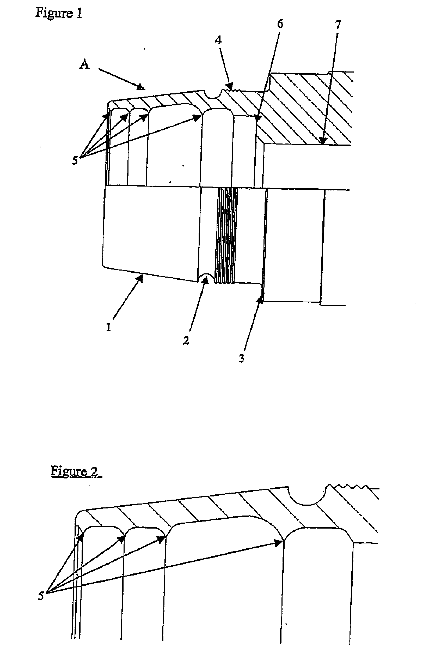
[0021]The interior annular protuberances on the inner body may compress the outside of the tube or like to which it is fitted. However, the interior annular protuberances preferably have a cutting surface to breach the skin of a tube or the like to which it is fitted. The skin of a tube or the like has a higher level of hardness than its core material resulting from its manufacture. By the cutting surface being able to breach the skin of a tube or the like to reach the softer core material, a superior seal and resistance to axial removal of the tube or like is obtained.
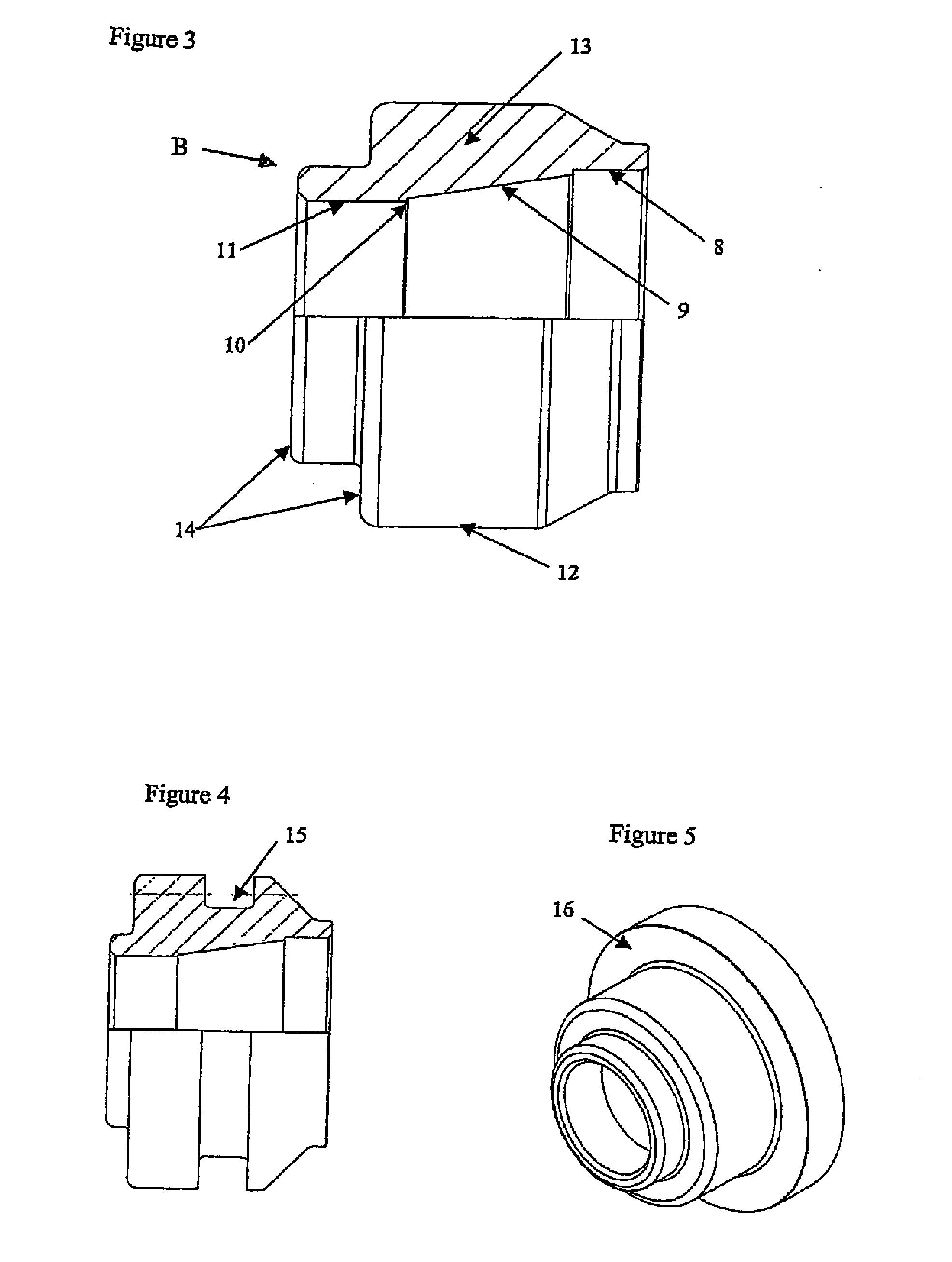
[0024]The collar may be arranged to apply a circumferential compressive force to deform the body in any suitable way, for example a so-called shaft clamp, hub clamp or hose type “jubilee” clamp may be used. However, the inner body and the collar preferably each have complimentary camming surfaces inclined to their axes which co-act to apply the circumferential compressive force to deform the body. The collar and the inner body are preferably arranged to be moved relatively towards each other so that the camming surfaces co-act. The collar and the inner body may be moved towards each other by any suitable means, such as by using an appropriate tool or by using corresponding threads on the inner body and collar such that the collar is rotated relative to the inner body to pull it over the inner body. The complimentary camming surfaces may be inclined at any desirable corresponding angles to provide a longer or shorter distance over which the inner body and collar may be moved towards each other. The complimentary camming surfaces may be provided by an external frusto-cone on the inner body and a corresponding frusto-conical inner surface within the collar. One or both of the camming surfaces could be provided with a friction reducing coating or plating to reduce the forces required during use.

Problems solved by technology

The following problems are associated with these designs:
This in itself can cause issues as traditional hardening methods such as nitriding induces carbon into the material, which reduces the surfaces corrosion resistance.
Incorrect tube preparation can cause major problems within the assembly of the fitting and this is one aspect that the manufacturer has no control over.
Longitudinal scratches on the tube can cause leak paths with these fittings.
Basic tube handling commonly causes these scratches.
These minor surface defects are often manually removed prior to assembly, which adds to the assembly time.
Due to the requirement of enhanced materials it is accepted that compression fittings manufactured from austenitic stainless steel are not suitable for use within certain environments and do not comply with the National Association of Corrosion Engineers (“NACE”) standards.
This is seen by a limitation within certain fields such as the automotive industry.

Method used


Image

  • Coupling
  • Coupling
  • Coupling

Examples


Embodiment Construction

[0044]The following examples discuss the invention being used in conjunction with a traditional tube. However the invention can also be used with a pipe, solid rod, wire rod or any other round section.

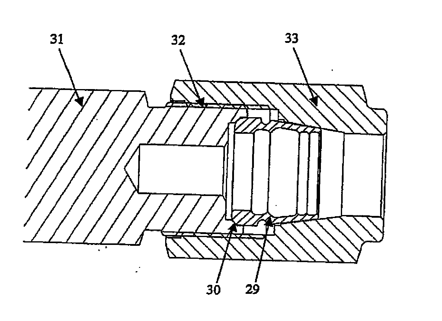
[0045]Embodiments of the invention include a method of attaching a coupling and a coupling that can for example, be machined into a traditional coupling, as will be shown in the following example, or machined onto existing equipment such as, but not limited to, valves, manifolds, pumps, hoses etc. The coupling comprises an inner body or a sealing member as shown for example in FIGS. 1 and 2 and a separate section or collar as shown for example in FIG. 3, which is used to modify the form of the sealing member.

[0046]The sealing member seals against a tube and also retains the tube in position. This member will be referred to as the claw end in the following description and is shown in FIGS. 1 and 2.

[0047]In this example the claw end A has an outside surface with an external frusto-cone 1...


PUM

PropertyMeasurementUnit
widthaaaaaaaaaa
radiiaaaaaaaaaa
lengthaaaaaaaaaa

Abstract

A coupling for attaching to an end of a tube, pipe, conduit or other round solid or hollow section. The coupling includes an inner body and a collar to be provided around the inner body. The inner body has an interior bore passing through at least a portion thereof to receive a tube and the bore has one or more interior annular protuberances extending into the bore. When the collar is provided around the inner body it applies a circumferential compressive force to deform the inner body such that the one or more annular protuberances engage the tube or the like to seal with it.

Description

CROSS REFERENCE TO RELATED APPLICATIONS[0001]This application is continuation of U.S. patent application Ser. No. 11 / 836,180, filed Aug. 9, 2007, which is a continuation of International Application No. PCT / GB06 / 000035, filed Feb. 17, 2006, which application designated the United States, and which application claims priority to Great Britain Patent Application No. 0502954.0, filed Feb. 25, 2005, and Great Britain Patent Application No. 0515165.9, filed Jul. 22, 2005, the disclosure of each of which applications is expressly incorporated herein by reference.BACKGROUND OF THE INVENTION[0002]The present invention relates to a coupling for attaching tubes, pipes, conduits and other round sections to other such items and / or other systems.[0003]Initially this invention has been developed within the instrumentation tube fittings industry. However, the invention is capable of being utilised within many other applications outside of this environment. Other applications may include shipbuildi...

Claims


Application Information

Patent Timeline
Patent Type & Authority Applications(United States)
IPC IPC(8): F16L19/08F16L13/14F16L19/10F16L19/14F16L37/138
CPCF16L13/146F16L19/10Y10T29/49927F16L37/138F16L19/14Y10T29/49934F16L13/14F16L21/007F16L21/08
Inventor NICHOLSON, SPENCER
Owner NICHOLSON SPENCER
Why Eureka
Try Eureka