Nozzle-typed drag-reducing structure for vehicle

a technology of drag reduction and nozzle, which is applied in the direction of roofs, transportation and packaging, vehicle arrangements, etc., can solve the problems of large vehicle size, poor fuel consumption efficiency, and large cost burden, etc., to enhance driving stability, increase the ability to resist deformation, and effectively boost the running efficiency

Inactive Publication Date: 2011-04-28
SMART ENERGY
View PDF36 Cites 40 Cited by
  • Summary
  • Abstract
  • Description
  • Claims
  • Application Information

AI Technical Summary

Benefits of technology

[0008]Therefore, in order to solve aforementioned problems, the invention is mainly to provide a nozzle-typed drag-reducing structure for vehicle, which can effectively guide the airflow passing around the vehicle and significantly reduce the drag when the vehicle is running. According to the invention, the running efficiency of the vehicle is promoted and the driving stability of the vehicle is enhanced.
[0010]Compared with prior arts, the invention further possesses the following functions and merits. First of all, whenever the vehicle is running in high speed or low speed, it is all possible for the invention to effectively boost the running efficiency and enhance the driving stability. Secondly, since of a plurality of separating plates installed in the frame body, it is possible for each deflector to increase its capability to resist the deformation. Finally, by means of the connecting assembly to be combined with the vehicle and the frame body, it is possible for the frame body to make adjustment by being swung relatively to the connecting assembly, which facilitates the rear door of the vehicle in processing the actions of open and close. Because of the assembling activation between the driving assembly and the connecting assembly, it can further enhance the operational convenience for the user.

Problems solved by technology

Because a large vehicle is heavier and larger than a small vehicle, so the large vehicle usually has a poor efficiency in terms of fuel consumption, compared with the small vehicle, during a long time and a long distance running, because of the drag problem, which further loads a larger amount of cost burden onto the industry, who runs the transportation business.
But, there is one problem existed; namely, if the running speed of the vehicle is lower than the specific value, then the dynamic energy of the airflow is too low to pass through the frame body.
In other words, the capability of the airflow to form the air wall is weakened, so it is impossible to reduce the eddy strength in a large scale and effectively, whereby the drag can not be reduced significantly, which is an issue needed to be addressed by the relative industry urgently.

Method used


Image

  • Nozzle-typed drag-reducing structure for vehicle
  • Nozzle-typed drag-reducing structure for vehicle
  • Nozzle-typed drag-reducing structure for vehicle

Examples


Embodiment Construction

[0022]In cooperation with attached drawings, the technical contents and detailed description of the present invention are described thereinafter according to a number of embodiments, not used to limit its executing scope. Any equivalent variation and modification made according to appended claims is all covered by the claims claimed by the present invention.

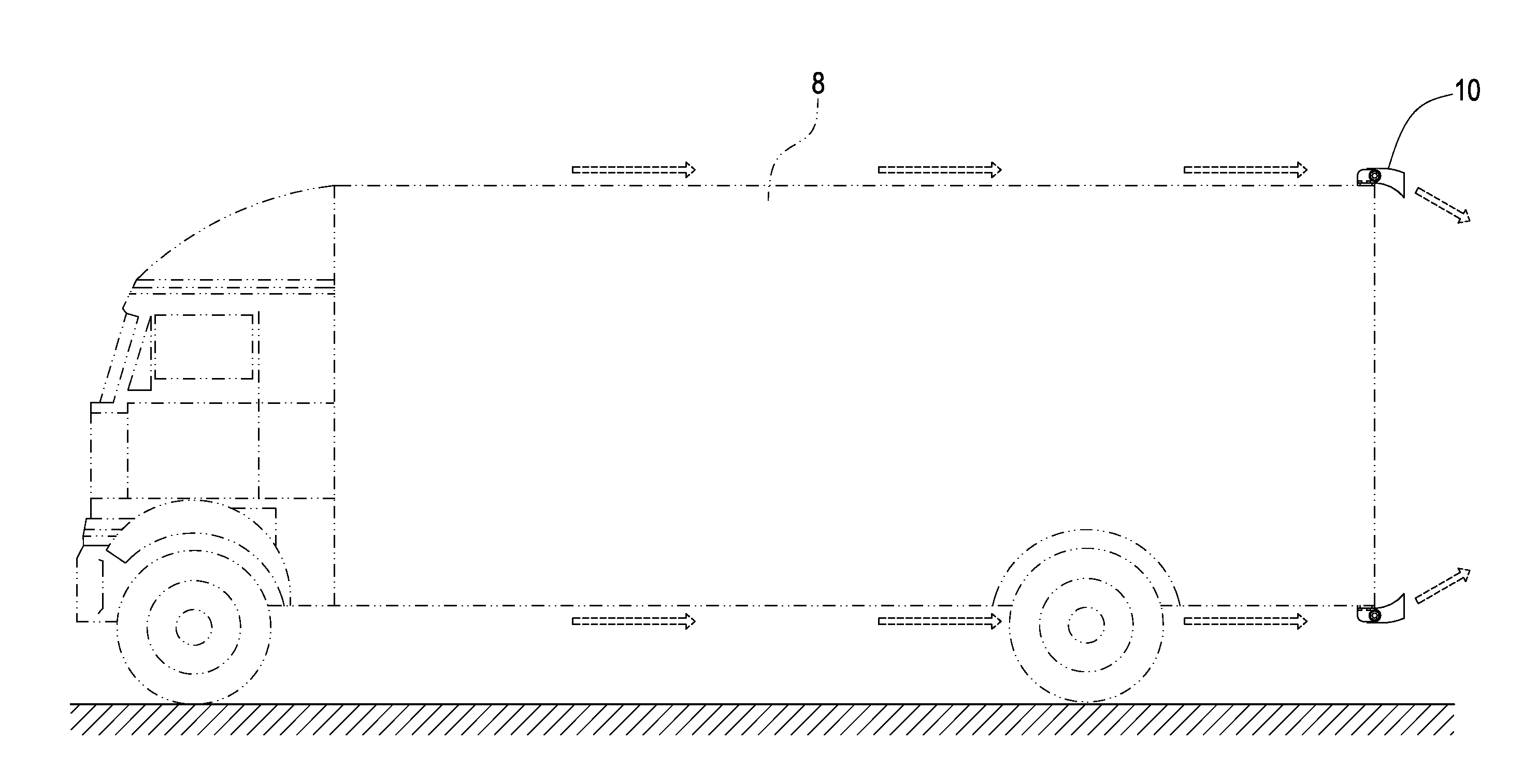
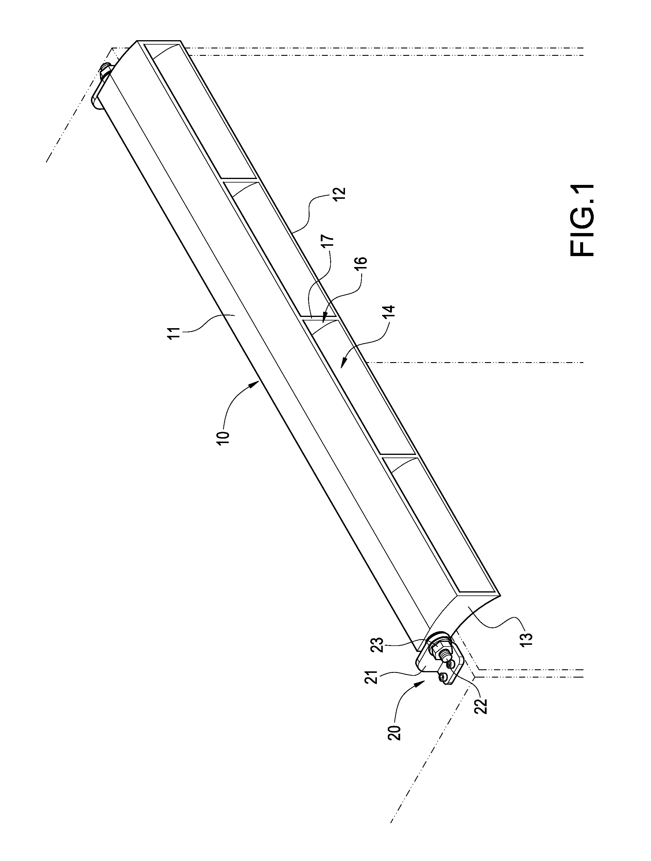
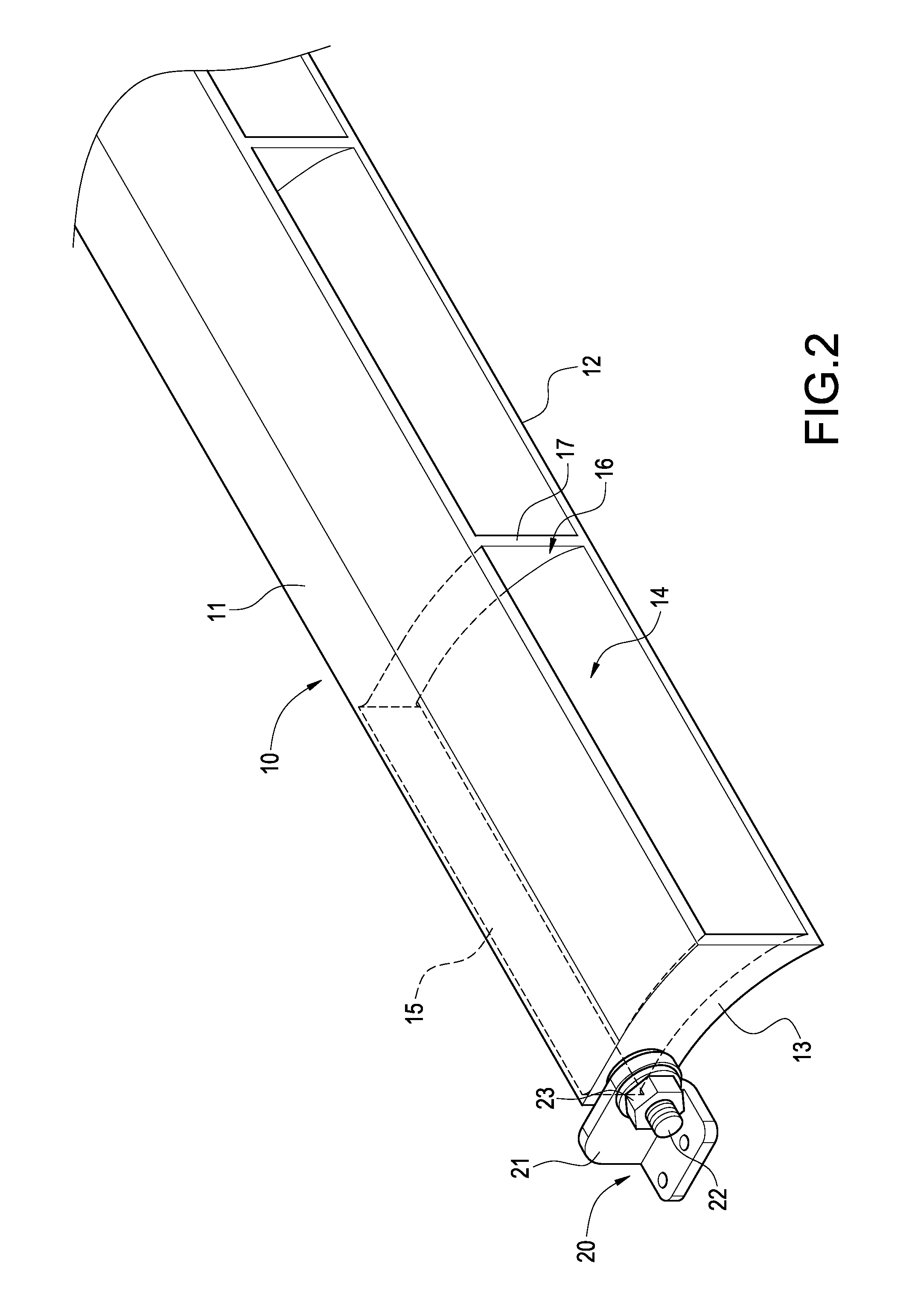
[0023]Please refer to FIG. 1 through FIG. 3, which show a nozzle-typed drag-reducing structure for vehicle according to the present invention, mainly including a frame body 10 and a pair of connecting assemblies 20.

[0024]The frame body 10 is integrally comprised of an upper deflector 11, a lower deflector 12 and two lateral deflectors 13. The upper and lower deflectors 11, 12 are all shown as an arc configuration individually, while the lateral deflectors 13 are shown as a vertical configuration respectively and interconnected with the upper and lower deflectors 11, 12. In addition, an airflow channel 14 is formed among each refl...


PUM


Abstract

A nozzle-typed drag-reducing structure for vehicle is arranged at the tail end of a vehicle, including a frame body comprised of a combination of a plurality of deflectors, between two of which an airflow channel is formed; and an air inlet and an air outlet respectively formed at two sides of the frame body, and the area comprised by surrounding the air outlet is larger than the area comprised by surrounding the air inlet. Thereby, whenever the vehicle is driven in high speed or low speed, it is all possible to boost the running efficiency and increase the driving stability.

Description

BACKGROUND OF THE INVENTION[0001]1. Field of the Invention[0002]The present invention in general relates to a drag-reducing structure, in particular, to a nozzle-typed drag-reducing structure for vehicle.[0003]2. Description of Prior Art[0004]When driven on road, the running efficiency of a common vehicle is usually influenced by the drag force of the surrounding airflow. The most common manner is to arrange deflector to solve this kind of problem. In particular, it is more necessary for a large vehicle to install reflector, when running in a long distance. Because a large vehicle is heavier and larger than a small vehicle, so the large vehicle usually has a poor efficiency in terms of fuel consumption, compared with the small vehicle, during a long time and a long distance running, because of the drag problem, which further loads a larger amount of cost burden onto the industry, who runs the transportation business.[0005]According to prior arts, as disclosed by Taiwan Patent No.: M...

Claims


Application Information

Patent Timeline
Patent Type & Authority Applications(United States)
IPC IPC(8): B62D37/02
CPCB62D35/001
Inventor CHEN, SHIH HSIUNG
Owner SMART ENERGY
Why Eureka
Try Eureka