Method for measuring current in an electric power distribution system

a technology of electric power distribution system and current sensor, which is applied in the direction of instruments, base element modifications, fault locations by conductor types, etc., can solve the problems of limiting the dynamic range, difficult to make a clamp-on version of the current sensor disclosed, and high cost and other issues to achieve the effect of reducing the danger of high voltage transfer

Active Publication Date: 2011-04-28
MICATU
View PDF40 Cites 12 Cited by
  • Summary
  • Abstract
  • Description
  • Claims
  • Application Information

AI Technical Summary

Benefits of technology

[0025]A further objective is to provide method for sensing current that includes control elements operably connected to the sensor only with optical fibers, and is properly grounded, so that there is reduced danger of high voltage transfer to the control elements.
[0026]A further objective is to provide a method for sensing current that enables several instruments to be operably connected to a current sensor for measuring several qualities of the current simultaneously.

Problems solved by technology

Optical current sensors that use bulk glass or fiber optic cable that surround the current carrying cable have very high dynamic range but require opening the current carrying cable at installation, hence are expensive.
However, due to saturation, the magnetic concentrator may limit the dynamic range.
A fully fiber optic or bulk current sensor can naturally be used for all applications but is expensive and cannot be clamped to the cable.
It is, however, difficult to make a clamp-on version of the current sensor disclosed.
This method requires installing a solid state electronics adjacent to the power cable and is therefore less reliable due to the exposure to the transients or the effects of lightning on the cable.
This compensation method is not accurate when there are changes in the installation.
Temperature and vibrations can induce errors in the readings of this form of detector.
This adds to the complexity and the cost.
The gain is optimized in a logarithmic way which is not suitable to optical current and voltage sensors, which must be linear in order to maintain the accuracy of the harmonics.
However, the prior art does not teach a low cost and simple sensor design for accurate measurements at large dynamic range, sensitivity and bandwidth, that is capable of being installed on the cable without disturbing the function of the cable.

Method used


Image

  • Method for measuring current in an electric power distribution system
  • Method for measuring current in an electric power distribution system
  • Method for measuring current in an electric power distribution system

Examples


Embodiment Construction

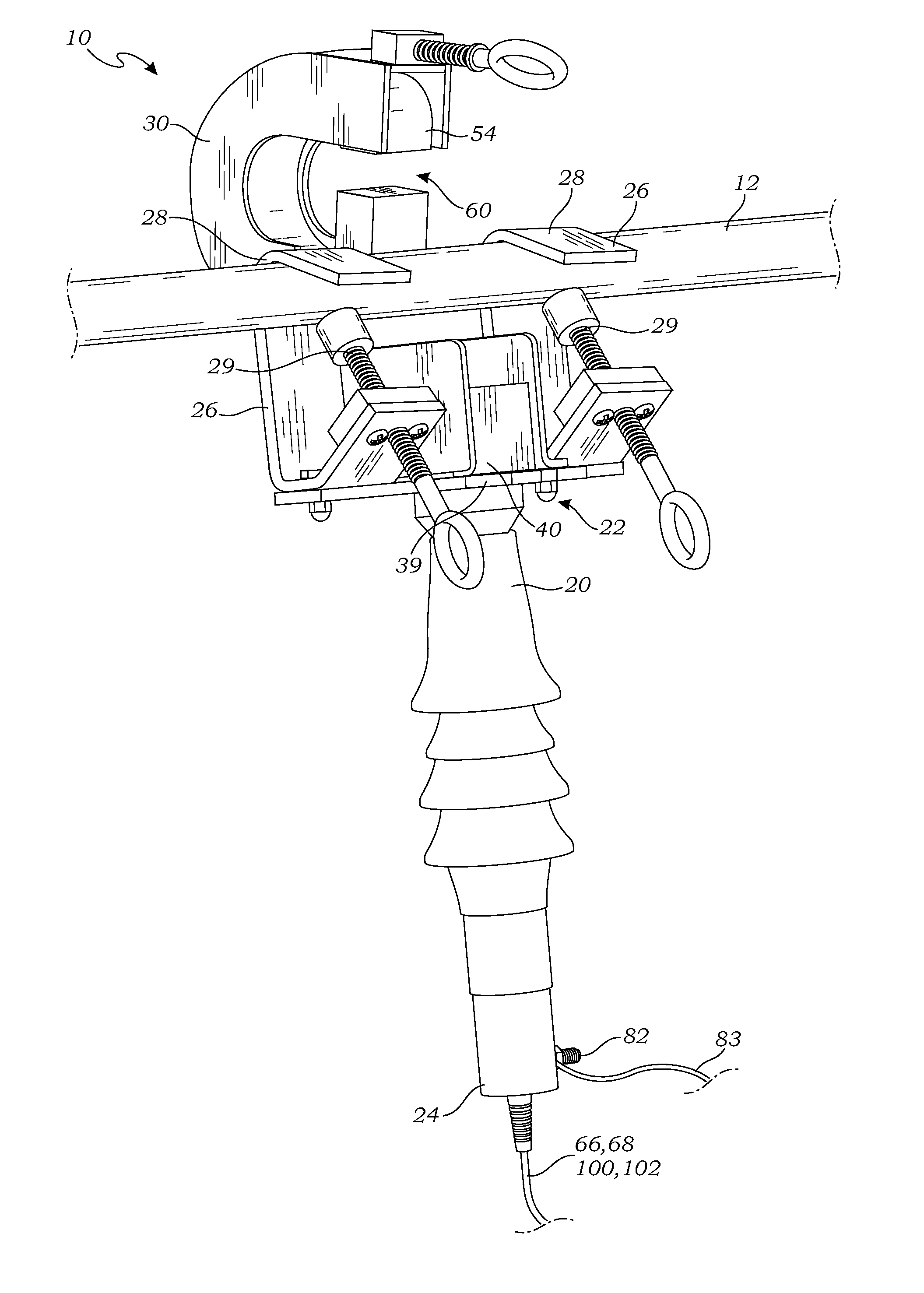
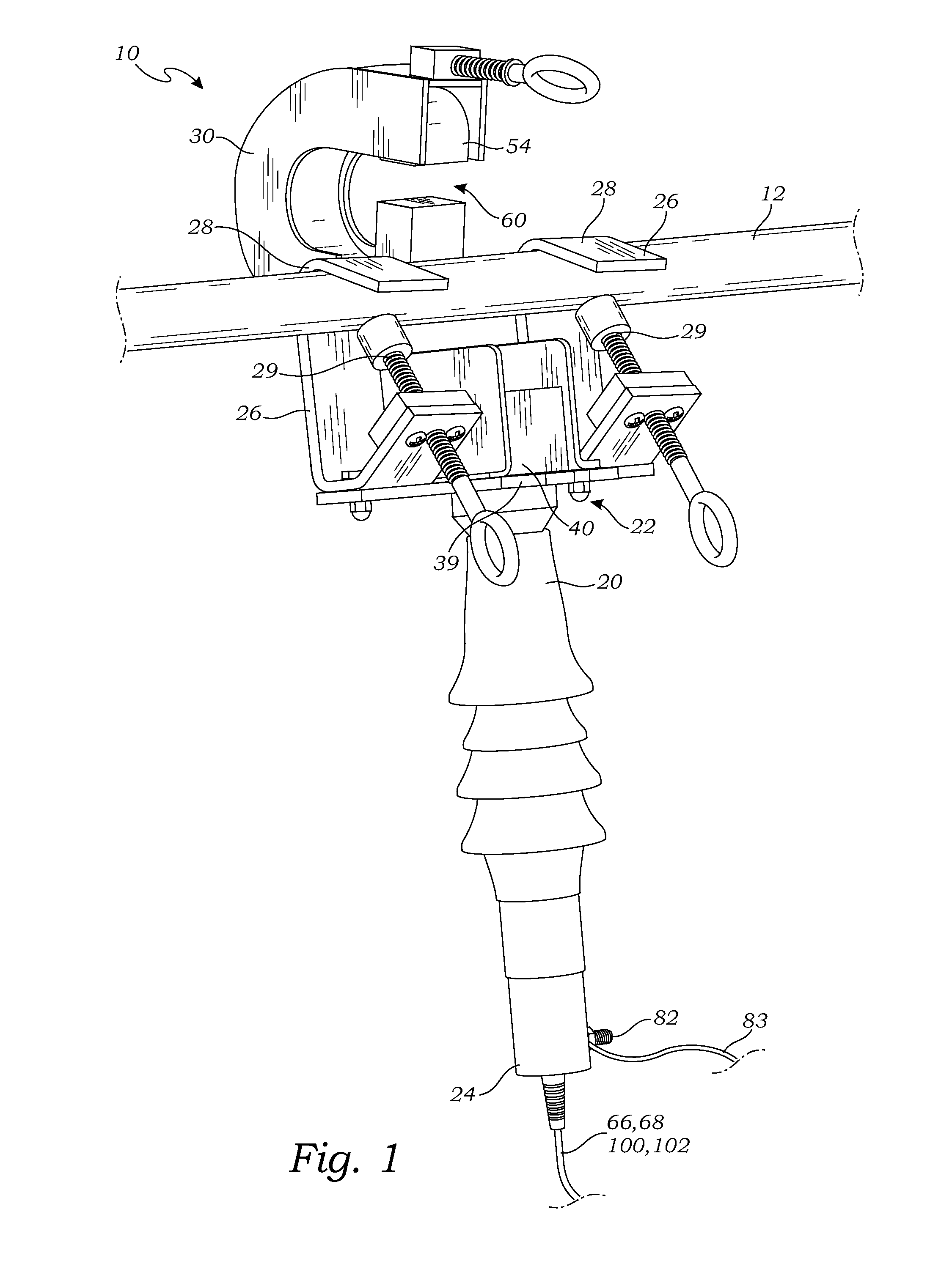
[0042]The above-described drawing figures illustrate the invention, an optical sensor assembly 10 for installation on a current carrying cable 12, particularly of a high voltage electricity distribution system, for measuring the current and voltage of the current carrying cable 12.

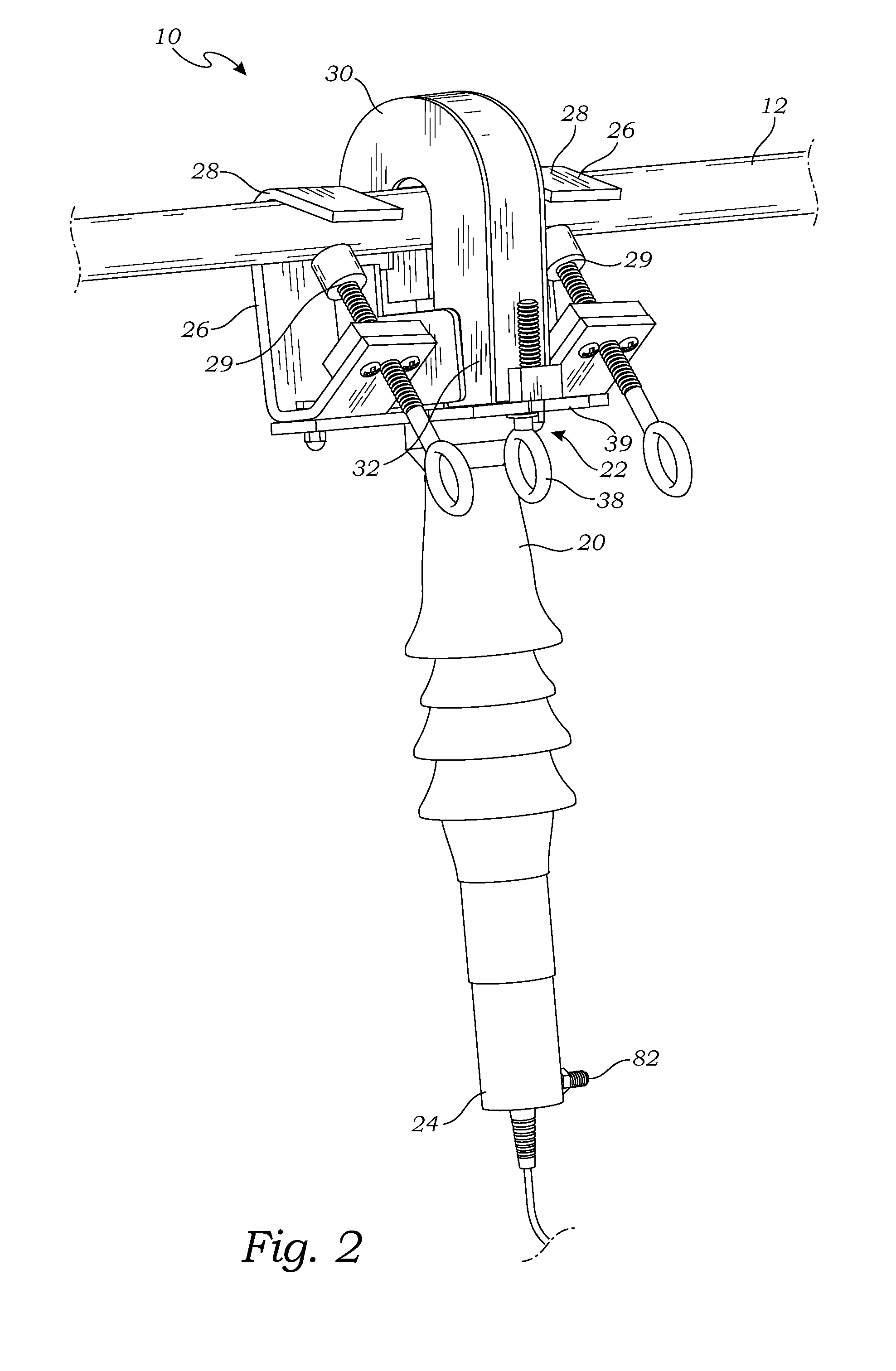
[0043]FIG. 1 is a perspective view of one embodiment of the optical sensor assembly 10 when a magnetic concentrator 54 is in the open position. FIG. 2 is the same perspective view illustrating the magnetic concentrator 54 in the closed position. FIGS. 3 and 4 represent their side elevation views respectively.

[0044]In the embodiment of FIGS. 1-4, the optical sensor assembly 10 comprises a base unit 20 having a top end 22 and a bottom end 24. In this embodiment, the base unit 20 is an elongate structure having an optical current sensor 40 mounted in the top end 22 and a voltage sensor 70 mounted near the bottom end 24. While thus arrangement is advantageous in the present embodiment, those skilled in the art...


PUM


Abstract

A method of measuring a current of a current carrying cable teaches the first step of providing an optical sensor assembly comprising a base unit, and an optical current sensor mounted on the base unit for transmitting a beam of polarized electromagnetic radiation to an optical fiber. A light detector is also provided having a first channel that operably connecting the light detector to an analog to digital converter through a programmable gain amplifier, a second channel that operably connects the light detector directly to the analog to digital converter, and a processor operably connected to the analog to digital converter. The optical sensor assembly is mounted adjacent the current carrying cable, and the fiber optic is operably connected to a light detector. A plurality of factors are then evaluated from rotation information from the light detector, by using the first and second channels for analog to digital conversion operably connected with the processor.

Description

CROSS-REFERENCE TO RELATED APPLICATIONS[0001]This application for a utility patent is a continuation-in-part of a previously filed utility patent, still pending, having the application Ser. No. 12 / 607,954, filed Oct. 28, 2009.STATEMENT REGARDING FEDERALLY SPONSORED RESEARCH[0002]Not ApplicableBACKGROUND OF THE INVENTION[0003]1. Field of the Invention[0004]This invention relates generally to a method for measuring current, and more particularly to a method for sensing both current and voltage levels in a current carrying cable of an electric power distribution system.[0005]2. Description of Related Art[0006]A variety of sensors have been developed for measuring the current in a current carrying cable, such as that of a high voltage electricity distribution system. Optical current sensors based on the Faraday effect are known in the art. Optical current sensors that use bulk glass or fiber optic cable that surround the current carrying cable have very high dynamic range but require op...

Claims


Application Information

Patent Timeline
Patent Type & Authority Applications(United States)
IPC IPC(8): G01R19/00G01R1/20
CPCG01R1/071G01R15/247G01R15/246G01R15/142G01R1/22G01N21/66G01R19/165G01R31/083
Inventor HARLEV, JOSEPH YOSSIVEAZEY, RHADJOHNSON, LEONARDKONETSKI, THEODORE
Owner MICATU
Why Eureka
Try Eureka