Power conversion apparatus
a technology of power conversion apparatus and power terminal voltage, which is applied in the direction of power conversion systems, electrical apparatus, ac-dc conversion, etc., can solve the problems of earth leakage circuit breaker tripping, noise generated due to fluctuation, and cost increase, and achieve the effect of suppressing the voltage of the power terminal
- Summary
- Abstract
- Description
- Claims
- Application Information
AI Technical Summary
Benefits of technology
Problems solved by technology
Method used
Image
Examples
first embodiment
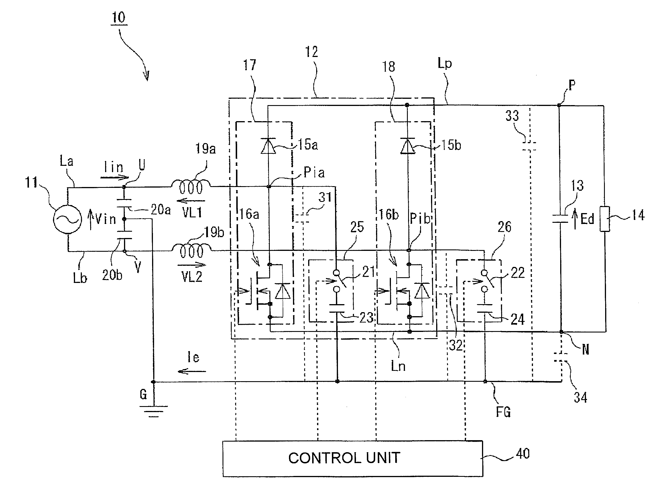
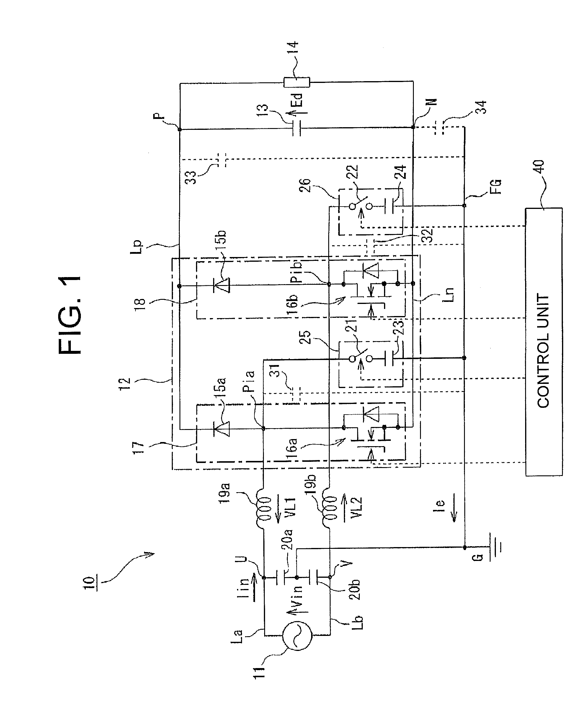
[0044]FIG. 1 is a circuit diagram showing a power conversion apparatus according to the invention. In FIG. 1, the reference numeral 10 represents a power conversion apparatus for driving a DC load. The power conversion apparatus 10 has, for example, a single-phase AC power supply 11, a rectification circuit 12, a smoothing capacitor 13 and a DC load 14. The rectification circuit 12 converts AC output power of the AC power supply 11 into DC power. The smoothing capacitor 13 smoothes the DC power outputted from a positive-side line Lp and a negative-side line Ln of the rectification circuit 12. The DC load 14 is connected between the positive-side line Lp and the negative-side line Ln.
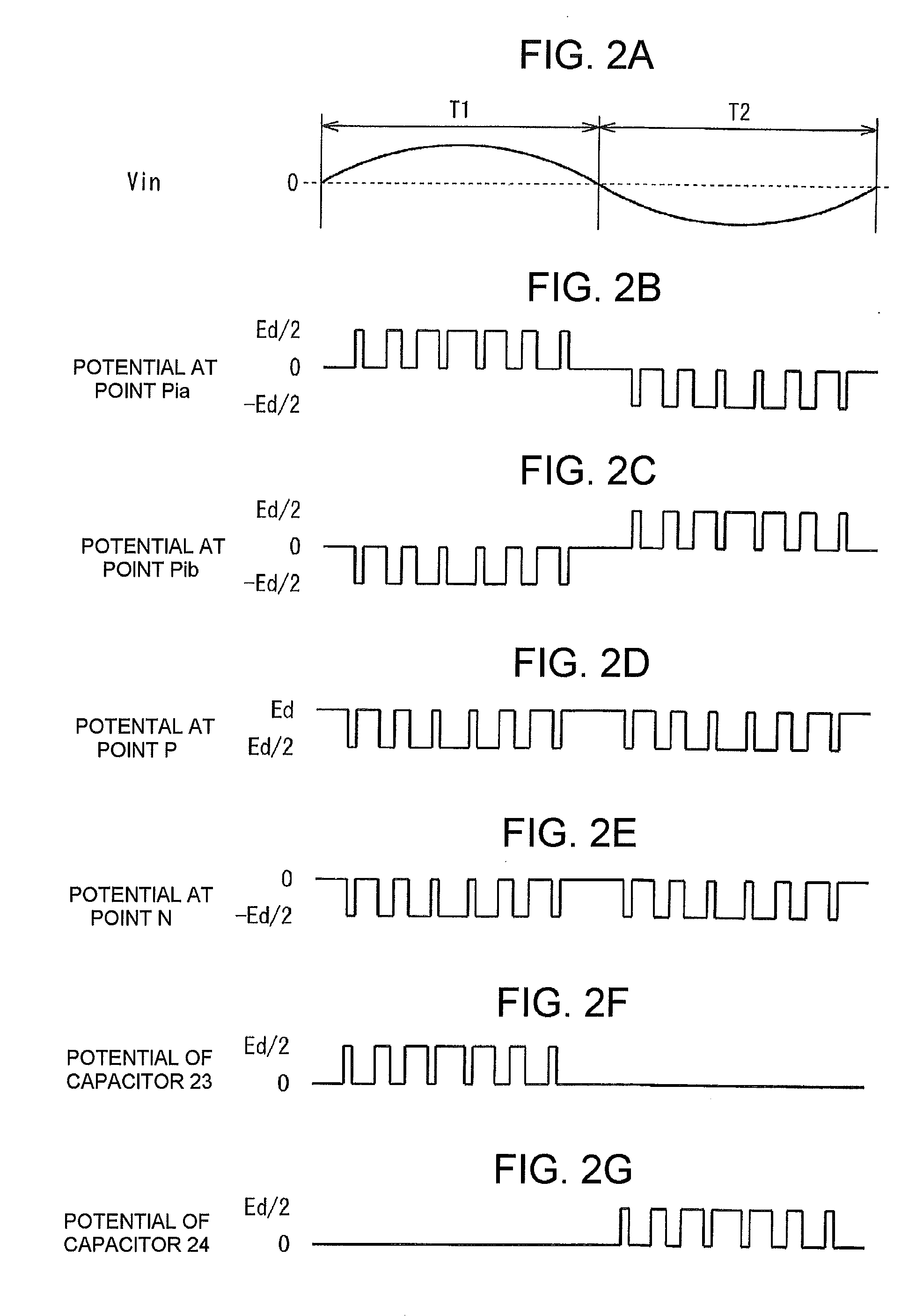
[0045]The rectification circuit 12 has a configuration in which series circuits 17 and 18 are connected in parallel between the positive-side line Lp and the negative-side line Ln. In each series circuit 17, 18, a diode 15a, 15b serving as a rectifying device and, for example, a MOSFET 16a, 16b serving a...
second embodiment
[0065]Next, the invention will be described with reference to FIG. 3.
[0066]In this second embodiment, a configuration is arranged so that switch circuits are prevented from being damaged during a withstand voltage test on the power conversion apparatus.
[0067]That is, the second embodiment has a similar configuration to that the first embodiment in FIG. 1, except that resistors 41 and 42 are connected in parallel to the switch circuits 21 and 22 as shown in FIG. 3. Parts corresponding to those in FIG. 1 are referred to by the same numerals, and detailed description thereof will be omitted.
[0068]In a power supply system, the power conversion apparatus 10 is often required to have a withstand voltage high enough to withstand an earth voltage. A withstand voltage test is performed with a voltage applied between the ground potential and one or both of input lines of the power conversion apparatus 10. The test voltage is set to be higher than a circuit operating voltage. The resistors 41 ...
third embodiment
[0074]Next, the invention will be described with reference to FIG. 4.
[0075]In this third embodiment, a capacitor to be connected in series with each switch circuit 21, 22 in the aforementioned first embodiment is shared between the switch circuits 21 and 22.
[0076]That is, as shown in FIG. 4, the third embodiment has the same configuration as the first embodiment in FIG. 1, except that the switch circuits 21 and 22 are connected to the ground potential G through a shared capacitor 51. Parts corresponding to those in FIG. 1 are referred to by the same numerals, and detailed description thereof will be omitted.
[0077]In this third embodiment, identical components are typically used as the diodes 15a and 15b and the MOSFETs 16a and 16b in the first embodiment in order to secure symmetry in the circuitry. Further, when the symmetric circuitry is secured structurally, the parasitic capacitances 31 and 32 also become substantially equal to each other. Hence, the required values of the capac...
PUM
 Abstract
Description
Claims
Application Information
 - R&D
- Intellectual Property
- Life Sciences
- Materials
- Tech Scout
- Unparalleled Data Quality
- Higher Quality Content
- 60% Fewer Hallucinations
Browse by: Latest US Patents, China's latest patents, Technical Efficacy Thesaurus, Application Domain, Technology Topic, Popular Technical Reports.
© 2025 PatSnap. All rights reserved.Legal|Privacy policy|Modern Slavery Act Transparency Statement|Sitemap|About US| Contact US: help@patsnap.com


