Method and system for seismic imaging and earth modeling using beam tomography

a beam tomography and seismic imaging technology, applied in the field of traveltime reflection tomography methods, can solve the problems of degraded seismic images, unfocused subsurface images, and often occurring multipathing of rays, and achieve the effect of improving earth model seismic velocities

Active Publication Date: 2011-04-28
CHEVRON CORP U S A
View PDF6 Cites 40 Cited by
  • Summary
  • Abstract
  • Description
  • Claims
  • Application Information

AI Technical Summary

Benefits of technology

[0006]Described herein are implementations of various embodiments of a beam tomography method and system for generating seismic images and earth models related to a subsurface region of the earth

Problems solved by technology

These misalignments are usually caused by incorrect seismic velocities which produce distorted, unfocused subsurface images.
Moreover, multipathing of rays often occu

Method used


Image

  • Method and system for seismic imaging and earth modeling using beam tomography
  • Method and system for seismic imaging and earth modeling using beam tomography
  • Method and system for seismic imaging and earth modeling using beam tomography

Examples


Embodiment Construction

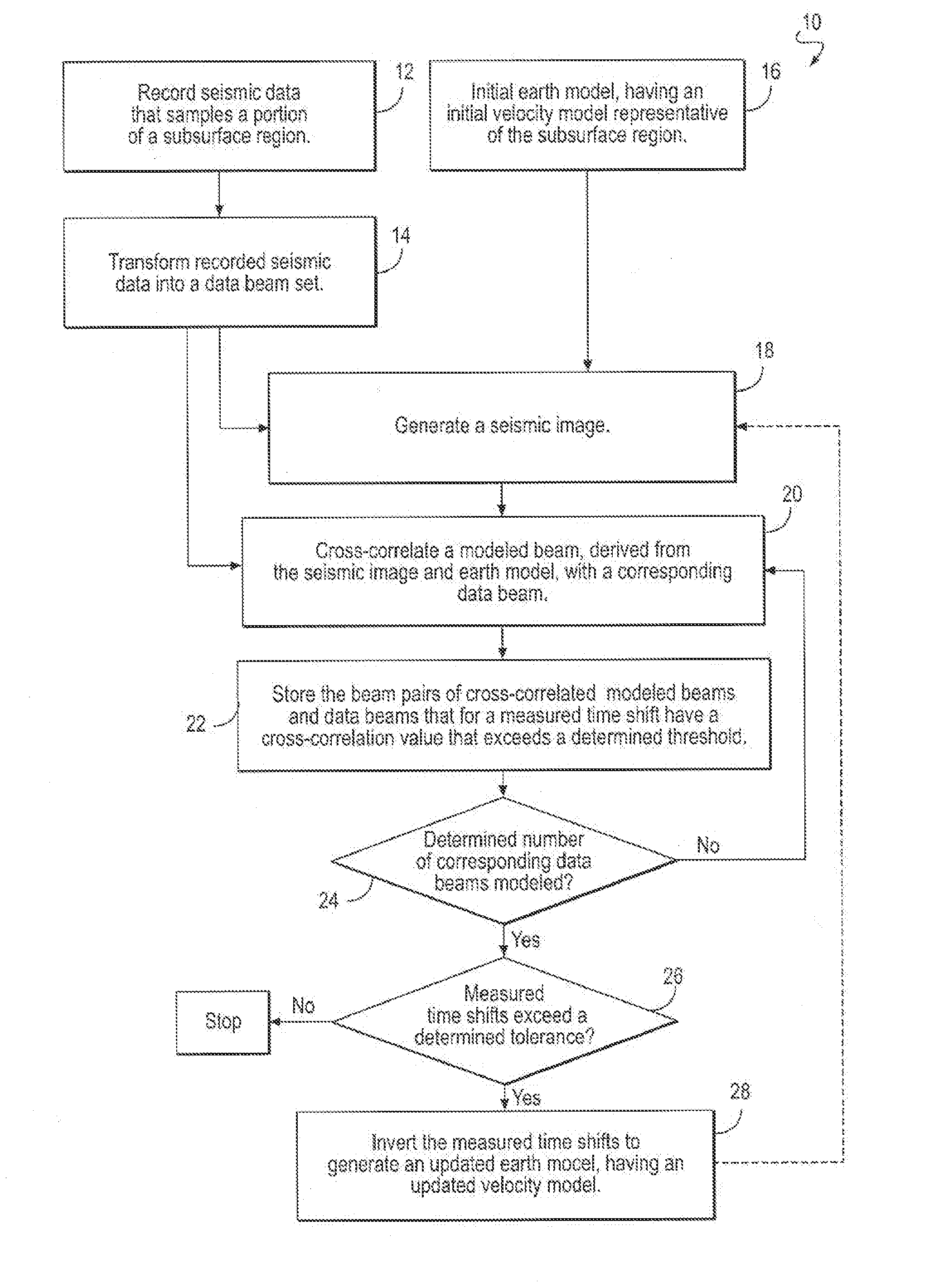
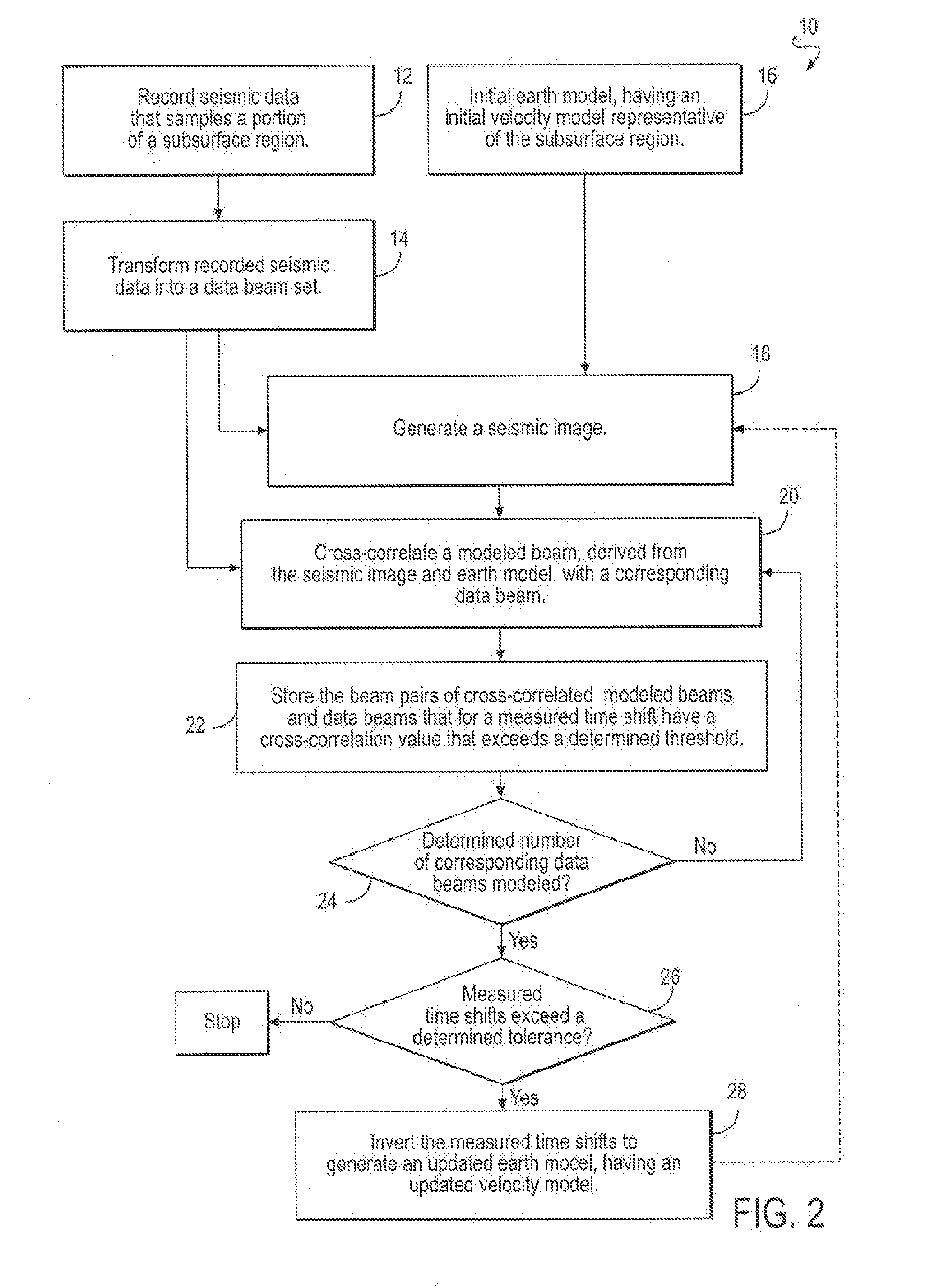
[0031]FIG. 2 illustrates a flowchart of a computer implemented method 10 for refining a seismic velocity model and generating seismic images related to a subsurface region of the earth, in accordance with one or more embodiments of the invention. The operations of method 10 presented below are intended to be illustrative. In some embodiments, method 10 may be accomplished with one or more additional operations not described, and / or without one or more of the operations discussed. Additionally, the order in which the operations of method 10 are illustrated in FIG. 2 and described below is not intended to be limiting.

[0032]In embodiments of the invention, method 10 starts at an operation where recorded seismic data 12, that samples a portion of the subsurface region, is transformed into a data beam set 14 and is stored in a computer storage media. The recorded seismic data samples a portion of the earth's subsurface and typically has undergone preliminary processing to increase the si...


PUM


Abstract

A beam tomography computer implemented method and system for generating improved seismic images and earth models without dependence on reflector structure is disclosed. Recorded seismic data is transformed into data beams which are compared to forward modeled beams using an earth model having a velocity model to compute raypaths and a seismic image to specify the reflectors. The tomographic updates to the earth model and velocity model are based on misalignments between the data beams and the same beams forward modeled from the velocity model and the seismic image. The updated earth model and seismic image better describe the true propagation of the beams through the earth.

Description

FIELD OF THE INVENTION[0001]The present invention relates generally to methods and systems for seismic imaging and earth modeling, and more specifically, to traveltime reflection tomography methods which utilize beams as input data for the method.BACKGROUND OF THE INVENTION[0002]In the field of petroleum exploration, images of the Earth's subsurface are required for reservoir exploration and development. Seismic images of a subsurface region of the Earth created with different subsets of the recorded seismic data are often misaligned. FIG. 1 is an example illustration of an image of the Earth's subsurface resulting from seismic data recorded at different offsets. The solid lines represent the seismic image using near-offset seismic data; the dashed lines represent the image produced by far offset seismic data. These misalignments are usually caused by incorrect seismic velocities which produce distorted, unfocused subsurface images. Measured misalignment values can be analyzed to co...

Claims


Application Information

Patent Timeline
IPC IPC(8): G01V1/28
CPCG01V2210/66G01V1/282G01V1/301
Inventor HILL, NORMAN ROSS
Owner CHEVRON CORP U S A
Why Eureka
Try Eureka