
High speed motion picture film processor

a high-speed, film-processing technology, applied in the direction of optics, instruments, photosensitive materials, etc., can solve the problems of severe vibration in the processor, excessive film tension, and increase in film tension or drag, so as to minimize the leakage of non-reactive gas

Inactive Publication Date: 2011-04-28
MICHELSON MANFRED G
View PDF5 Cites 0 Cited by
  • Summary
  • Abstract
  • Description
  • Claims
  • Application Information

AI Technical Summary

Benefits of technology

[0010]In a separate group of aspects of the present invention, the high speed motion picture film processor also has a gas make-up system for adding a non-reactive gas (such as nitrogen) inside of the developer tank and a system of seals to minimize leakage of the non-reactive gas from inside of the developer tank outside of the developer tank. The system of seals includes a first seal along a periphery of the developer tank below a sprocket level plus a tank cover and a second seal along a second periphery of the tank cover above the sprocket level, the sprocket level being determined by a centerline of a shaft that supports a plurality of sprockets used for high speed processing of film inside of the developer tank.
[0011]In another, separate group of aspects of the present invention, the first and the second seals are barriers, such as a knife-edge, with a lower end in a liquid reservoir which is filled with the developer solution by operation of the high speed motion picture film processor when the high speed motion picture film processor is in operation. Both the liquid reservoir and the barrier are constructed so as to allow movement of the barrier within the liquid reservoir without allowing the non-reactive gas to exit the developer tank when the high speed motion picture film processor is in operation. The liquid reservoirs are formed by an outer wall, a trough and an inner wall, and the height of the inner wall is less than the height of the outer wall so that when the liquid reservoir overflows any overflow will flow over the inner wall into the developer tank. A mechanism (such as an overpressure relief valve) may also be used to prevent the tank cover from being lifted up by the positive pressure inside of the developer tank.
[0015]In still a further, separate group of aspects of the present invention, the sprocket shaft in the developer tank has a two small shafts mounted on two sets of bearings (which may be metal bearings) inside two beams with two flexible seals for preventing gas from leaving the developer tank on two sides of the developer tank opposite each other and a tube (which may be solid, but is preferably hollow) with a larger diameter than the small shafts is affixed at each of its ends to one of the small shafts, while sprockets are mounted on the tube. Rotational and lateral movement of the sprockets on and relative to the tube can be prevented. One way to prevent rotational movement of the sprockets is to use pins inserted through the tube and held in place by opposing indents formed in the sprockets. The inside of the two beams can be slightly pressurized relative to the positive pressure of the developer tank.

Problems solved by technology

The problem with processing at high speeds is that the film tension or drag increases drastically as the speed increases.
At processing speeds above 1000 feet per minute the film tension becomes excessive due to solution drag.
An additional problem which occurs at high speed is the whirling, or bending, of the sprocket shaft 3 which causes severe vibrations in the processor.
The problem with the primary solution is that the developer will oxidize when exposed to excessive amounts oxygen.
In previous attempts to do this the developer tank 2 was not properly sealed, the oxygen concentration was not monitored, the tank 2 pressure was not monitored and the film entry and exit ports were not properly sealed.

Method used


Image

  • High speed motion picture film processor
  • High speed motion picture film processor
  • High speed motion picture film processor

Examples


Embodiment Construction

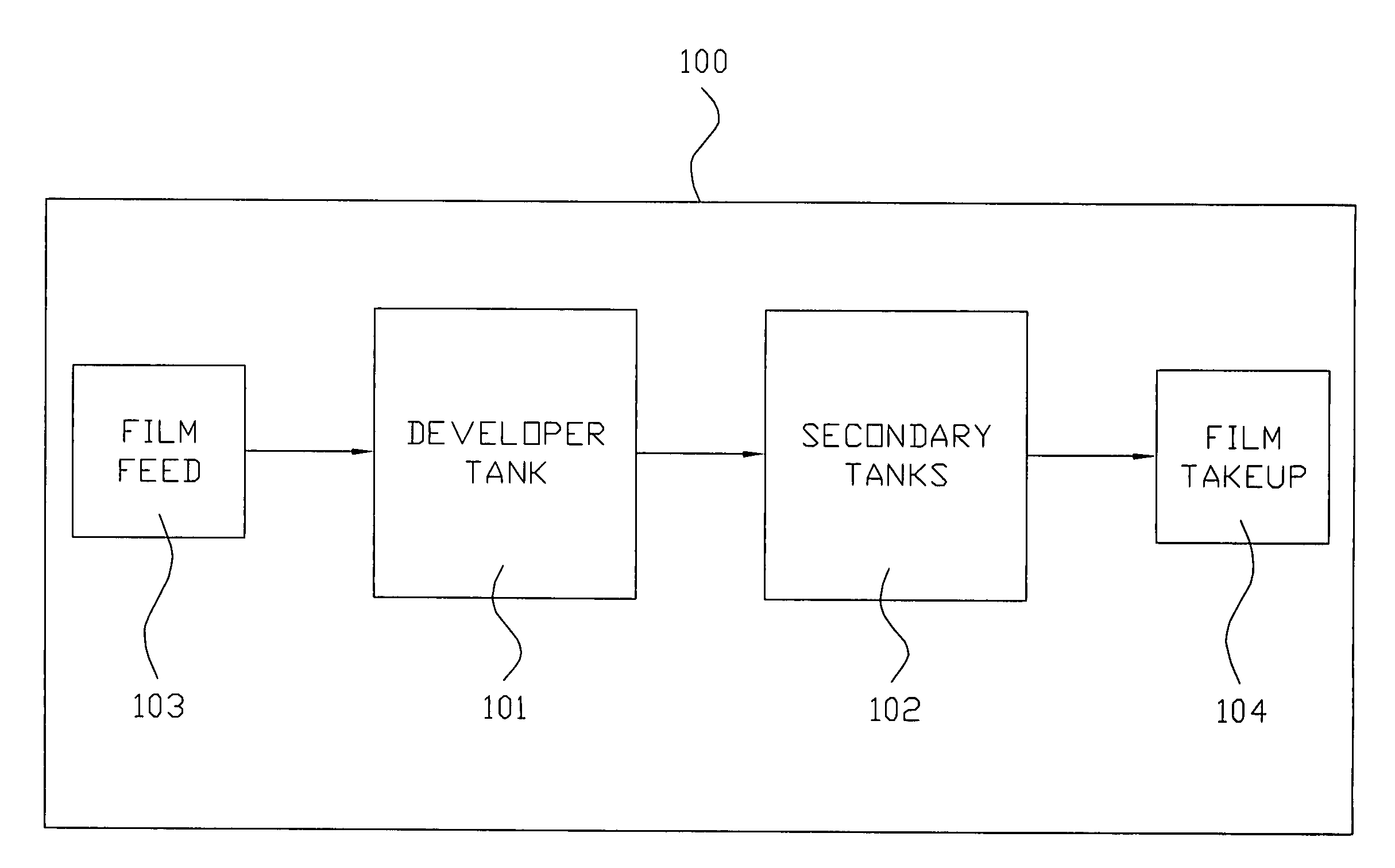
[0032]In accordance with the present invention, a high speed motion picture film developer is disclosed that can be represented in a simplified schematic diagram as shown in FIG. 10. The high speed motion picture film developer, shown generally as 100, has a film feed 103 to developer tank 101 and then secondary tanks 102 and a film takeup 104.

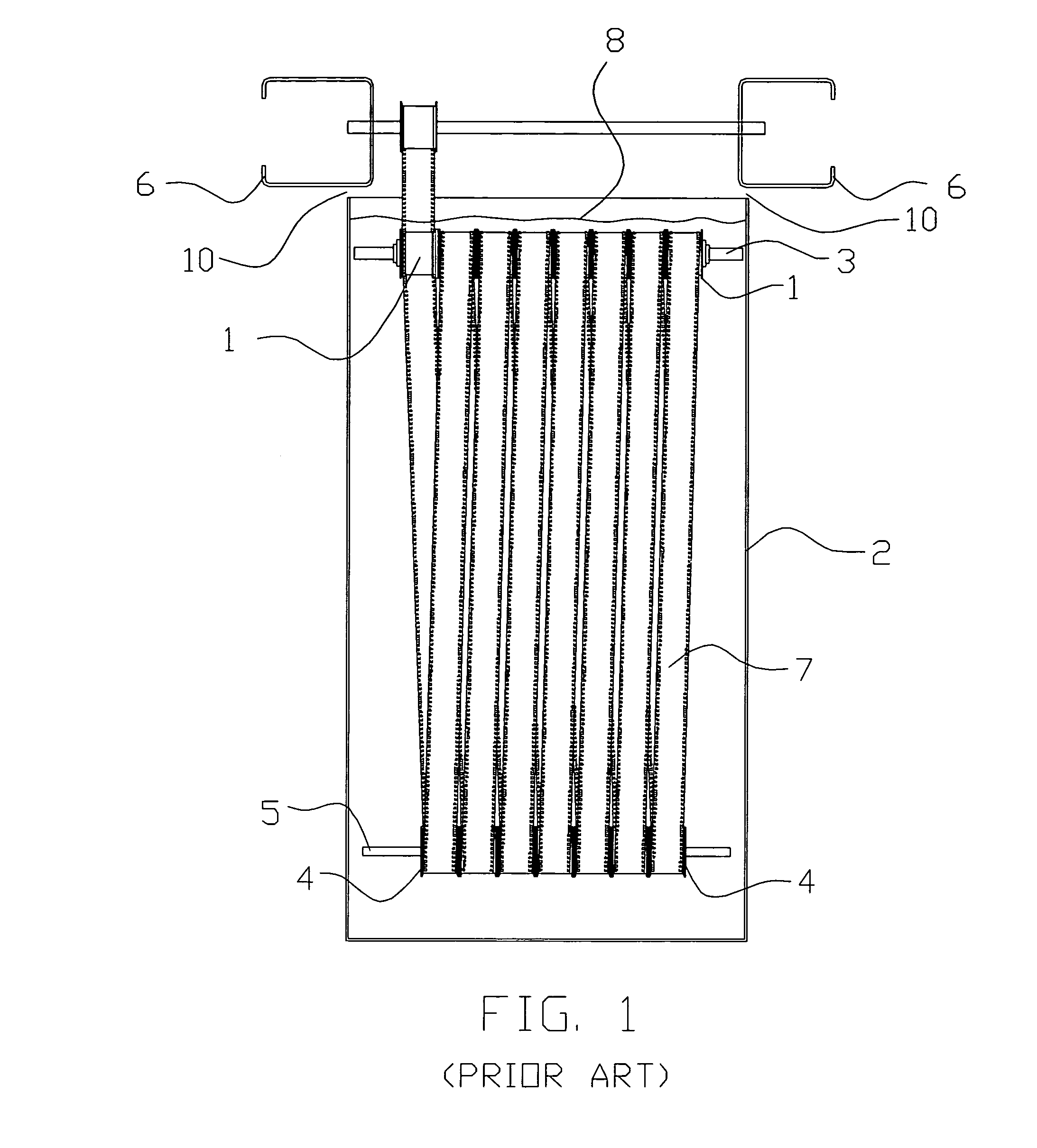
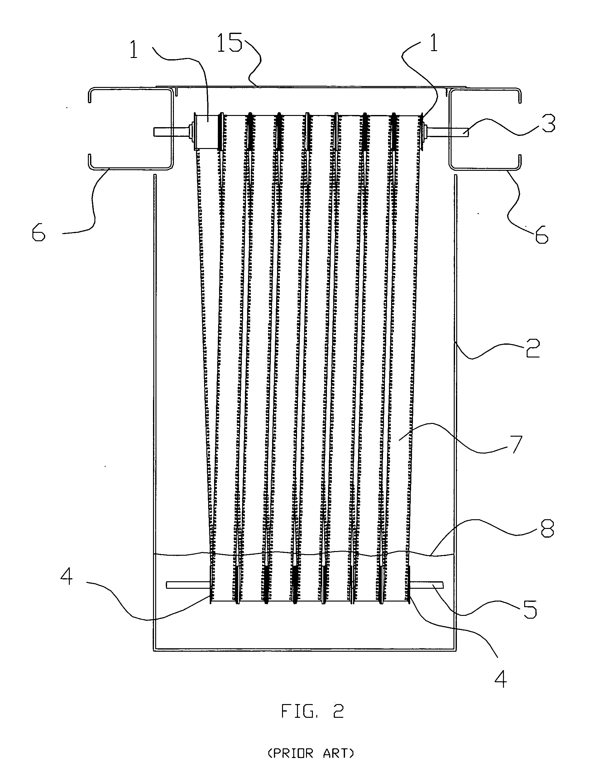
[0033]The present invention will now be described in connection with several especially preferred embodiments that illustrate various aspects of the inventive concepts described herein. In the Figures and the following more detailed description, numerals indicate various features of the invention, with like numerals referring to like features throughout both the drawings and the description. Although the Figures are described in greater detail below, the following is a glossary of the elements identified in the Figures:[0034]1 Sprocket[0035]2 Tank[0036]3 Sprocket Shaft[0037]4 Roller[0038]5 Roller Shaft[0039]6 Beam[0040]7 Film[0041]8 Solution L...


PUM


Abstract

A high speed motion picture film processor has a developer tank having a positive pressure relative to an ambient air pressure outside of the tank. A gas make-up system adds nitrogen inside of the developer tank while a system of seals minimizes leakage. Two seals are used along a periphery of the developer tank; one is below a sprocket level while the other is above the sprocket level. These two barriers can utilize a liquid reservoir that is filled by operation of the processor with excess liquid returning to the developer tank and they are constructed so as to allow movement. A film entrance sealing device and a film exit sealing device, each with its own housing, are also used with the developer tank; these units use a pair of rollers and a pair of flexible barriers to separate a tank gas chamber from an air chamber which is at a lower pressure and which contains a partial pressure of nitrogen fed into the entrance sealing device. The level of developer fluid is maintained at approximately the centerline of a first roller shaft but below that of a second roller shaft. The sprocket shaft has two smaller shafts mounted in metal bearings and a center tube on which the sprockets are mounted. Oxygen sensors with throttling exhaust devices outside the developer tank sound an alarm when oxygen level is too high in the developer tank. Reservoir fluid seals may also be used on secondary tanks.

Description

FIELD OF THE INVENTION[0001]This invention is in the field of high speed motion picture film processors.BACKGROUND OF THE INVENTION[0002]Generally, the processing, sometimes also referred to as developing, of motion picture films consists of passing an exposed film though numerous different chemical solutions.[0003]Modern film processors, sometimes referred to as film developers, consist of a set of tanks, sprockets, and rollers. FIG. 1 shows one such tank 2. The sprockets 1 usually located on a sprocket shaft 3, located in the top of the tank or on top of the tank 2 pull the film 7 over a set of rollers 4 mounted on a roller shaft 5, usually located in the bottom of the tank 2. The sprocket shaft 3 rotates, thus rotating sprockets 1 and transporting the film. The distance between the top and bottom shaft may vary between 3 and 10 feet. The number of sprockets 1 on sprocket shaft 3 may vary from a single sprocket, for very a low speed processor, to up to twenty sprockets for a large...

Claims


Application Information

Patent Timeline
IPC IPC(8): G03D3/02
CPCG03D3/132
Inventor MICHELSON, MANFRED G.
Owner MICHELSON MANFRED G
Learn More