
Optical communication system, optical transmitter, optical receiver and methods, and correlators used therefor

a communication system and optical transmitter technology, applied in the field of optical communication systems, can solve the problems of difficult to obtain compact ssfbg-type encoder/decoder, difficult to finish polynomial time search, difficult to obtain important information, etc., and achieve the effect of keeping cross-correlation values low

Inactive Publication Date: 2011-04-28
UNIVERSITY OF YAMANASHI
View PDF3 Cites 16 Cited by
  • Summary
  • Abstract
  • Description
  • Claims
  • Application Information

AI Technical Summary

Benefits of technology

[0013]A further object of the present invention is to so arrange it that interference in code multiplexing can be reduced in an optical receiver.
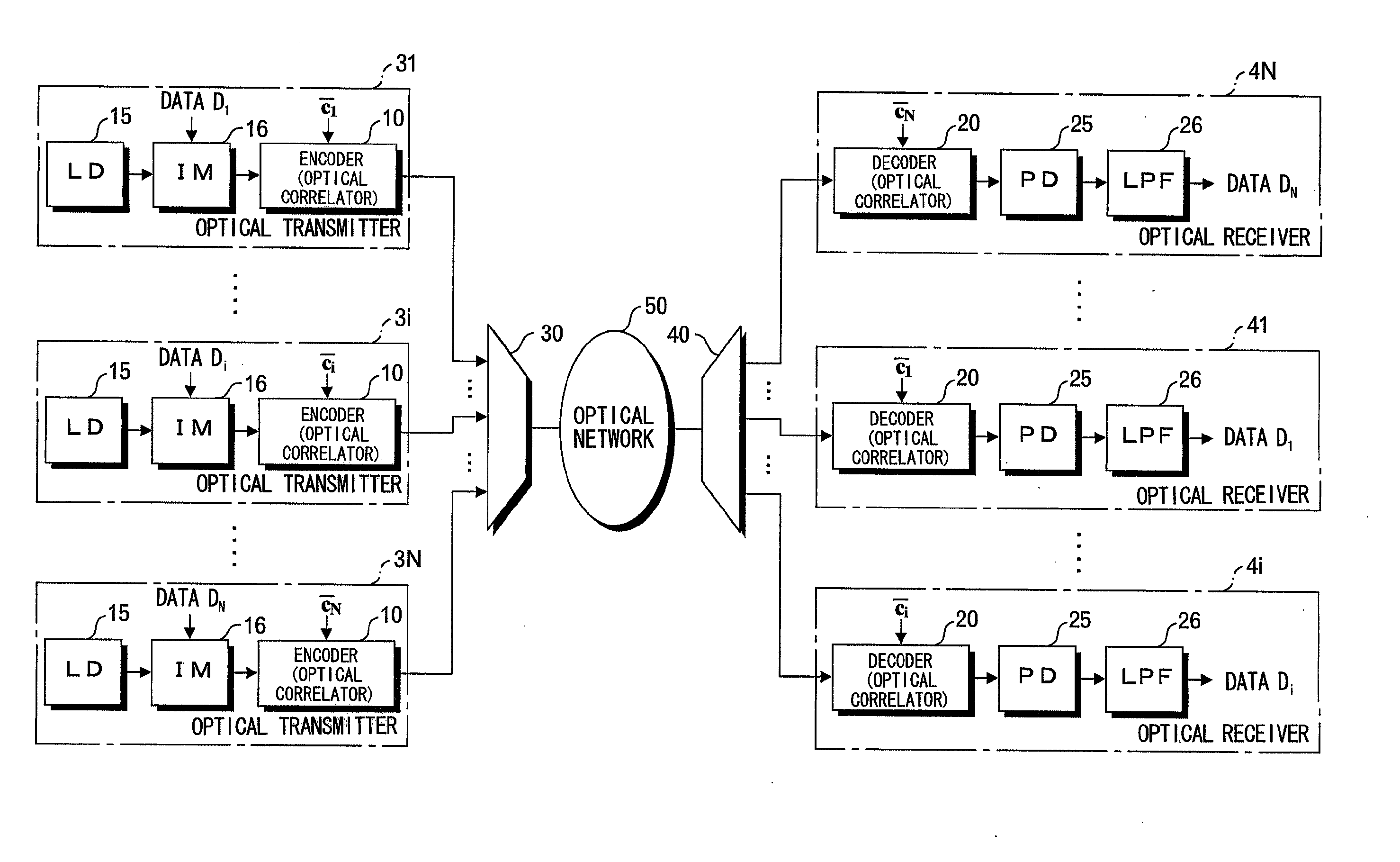
[0020]The optical receiver further has a photoelectric converting circuit for photoelectrically converting an optical correlation signal, which is output from the optical correlator, and outputting an electrical signal; and a low-pass filter for reducing (blocking) multiplexed interference signals, which have been produced owing to encoding by code words of complex orthogonal codes other than the code word that has been allocated to the optical correlator, from the output electrical signal of this photoelectric converting circuit. As a result, multiplexed interference signals encoded by complex orthogonal codes other than that desired can be reduced. That is, a reduction in optical code division multiplex noise is realized.
[0029]Thus, in accordance with the present invention, it is possible to realize an optical communication system, an optical transmitter, an optical receiver and an optical correlator that employs complex orthogonal codes for OCDM / OCDMA suited to encoding / decoding based upon optical processing, in which cross-correlation values are kept low.

Problems solved by technology

Further, with a binary Hadamard code, code combinations in which the side lobes of cross-correlation signals cannot be reduced exist, and the binary Hadamard code can only be used in synchronous OCDM / OCDMA in which all multiplexed / multiple channels are synchronized.
This makes it difficult to obtain a compact SSFBG-type encoder / decoder.
However, since a code cannot be obtained systematically, it is difficult in practice to obtain important information, such as the maximum number of code sequences and maximum cross-correlation value capable of being acquired in a certain code length.
Further, it is required that the conversion matrix be found using a heuristic search algorithm, and as code length grows longer, it is difficult to finish the search in polynomial time.

Method used


Image

  • Optical communication system, optical transmitter, optical receiver and methods, and correlators used therefor
  • Optical communication system, optical transmitter, optical receiver and methods, and correlators used therefor
  • Optical communication system, optical transmitter, optical receiver and methods, and correlators used therefor

Examples


Embodiment Construction

[0042]A code used in optical communication based upon Optical Code Division Multiplexing (OCDM) or Optical Code Division Multiple Access (OCDMA) in the present invention is a complex orthogonal code of code length N using as a code word each row of an N×N square matrix in which an element of an mth row and nth column is represented by the following:

exp⌊j2π(m-1)(n-1)N⌋Eq.(1)[0043](m,n=1, 2, . . . , N)[0044](j is an imaginary unit)

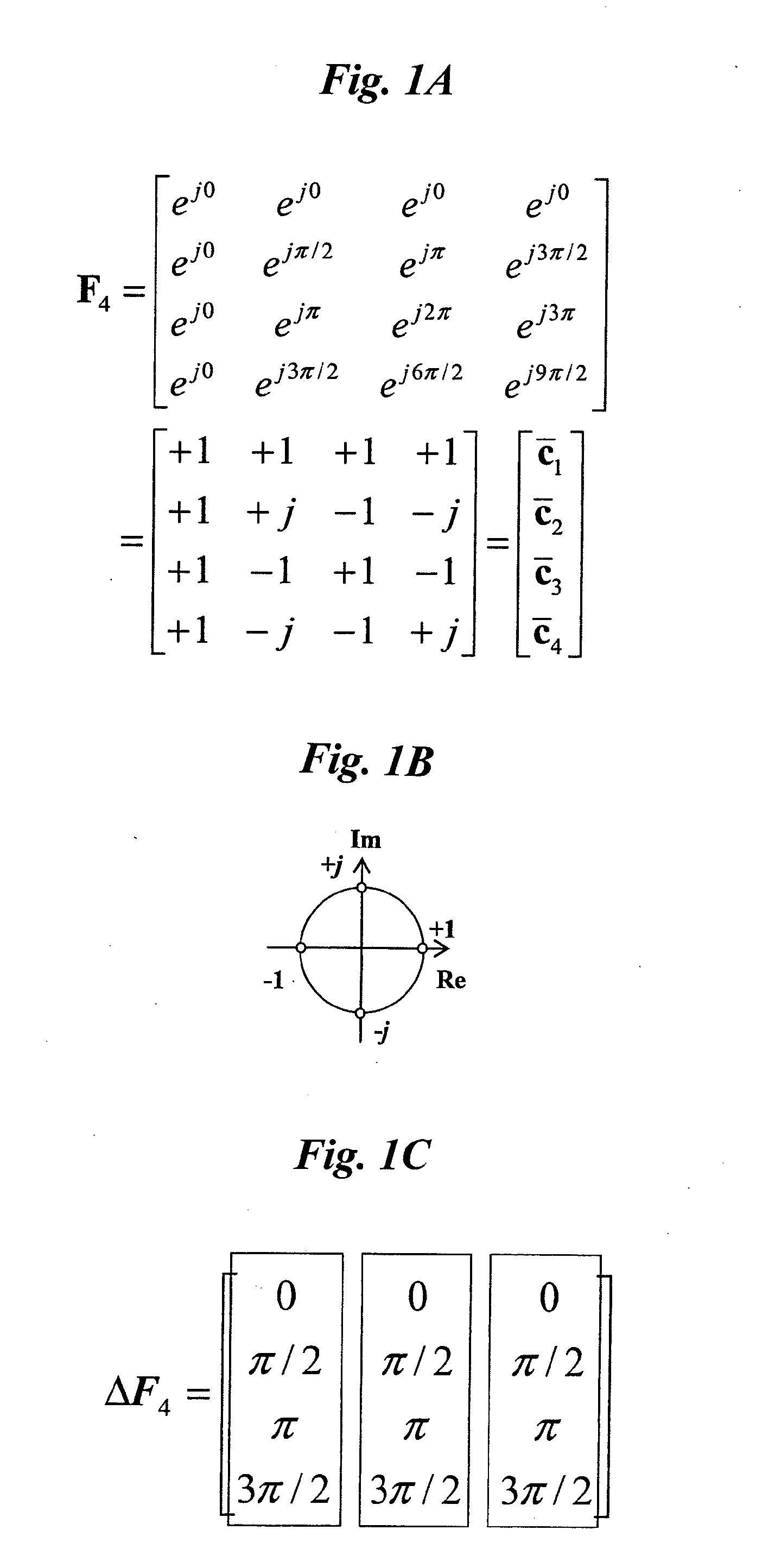
[0045]An example of a square matrix that gives complex orthogonal codes in a case where N=4 holds is represented in FIG. 1A [this shall be referred to as “Equation (2)]. Rows c1, c2, c3, c4 are respective code words based upon the complex orthogonal code [in this specification, the bar over ci (i=1 to N) is omitted]. The meaning of each code can be understood in the complex plane shown in FIG. 1B.

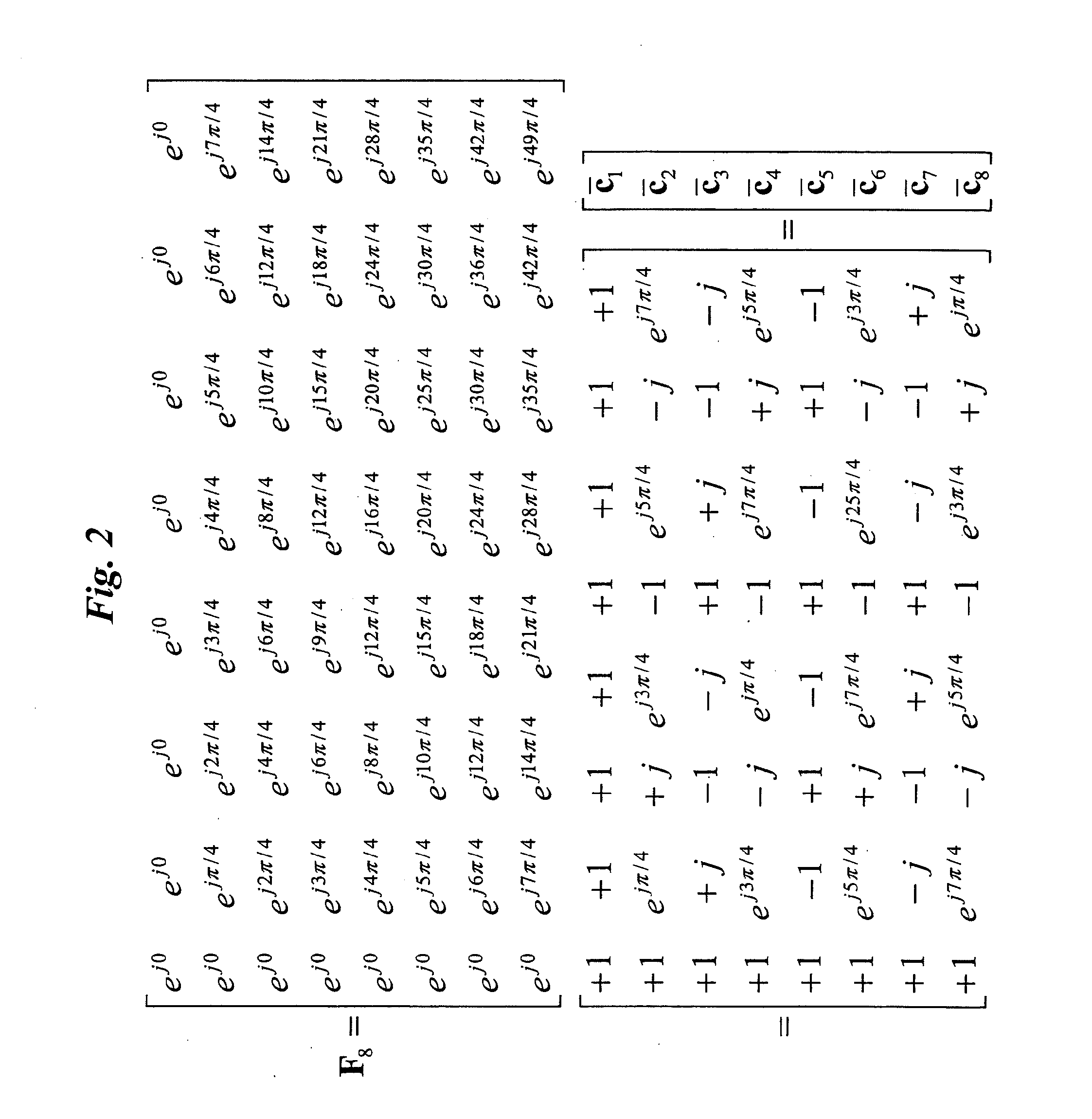
[0046]An example of a square matrix that gives complex orthogonal codes in a case where N=8 holds is represented in FIG. 2 [this shall be referred to as “Equation (...


PUM


Abstract

A complex orthogonal code in the present invention is one in which each row of a square matrix of N rows and N columns in which an element of an mth row and nth column is exp[2πj(m−1)(n−1) / N] (where j is an imaginary unit) is adopted as a code word. An optical orthogonal code for Optical Code Division Multiplexing / Optical Code Division Multiple Access (OCDM / OCDMA) is realized by a train of N-number of optical pulses corresponding to the argument (phase) of the code elements. An optical transmitter or optical receiver includes an optical correlator provided with a sampled Bragg grating having a plurality of Bragg gratings disposed serially at regular intervals inside an optical waveguide. The optical correlator is allocated any one of the code words. In the optical transmitter, an optical signal to be transmitted is encoded by the optical correlator. In the receiver, a received optical signal is decoded by the optical correlator. A high autocorrelation output is obtained only in a case where the code word used to encode the received optical signal and the code word allocated to the optical receiver match.

Description

TECHNICAL FIELD[0001]This invention relates to an optical communication system. More particularly, the invention relates to an optical communication system that employs Optical Code Division Multiplexing (OCDM) or Optical Code Division Multiple Access (OCDMA), an optical transmitter and optical receiver for this system, an optical communication method, optical transmission method and optical receiving method, and correlators used therefor.BACKGROUND ART[0002]With Code Division Multiplexing / Code Division Multiple Access, multiplexing / multiple access is realized utilizing code orthogonality. With these systems, an orthogonal code functions as one type of key. A signal encoded by an orthogonal code is capable of being received only by an autocorrelation signal obtained in a case where the signal has been decoded by the same orthogonal code; it is not receivable with a cross-correlation signal obtained in a case where the signal has been decoded using a different orthogonal code. This t...

Claims


Application Information

Patent Timeline
IPC IPC(8): H04B10/08G02F1/01H04B1/707H04B10/00H04J13/18H04J14/00H04J14/04H04J14/06
CPCH04J11/0033H04J11/005H04J14/02H04J14/007H04J13/18
Inventor HANAWA, MASANORI
Owner UNIVERSITY OF YAMANASHI
Learn More