
Cochlear implant

a technology of cochlear implants and cochleas, applied in the field of cochlear implants, can solve problems such as inability to meet patients, and achieve the effect of improving hearing and speech ability

Inactive Publication Date: 2011-04-28
SPEARMAN MICHAEL R +1
View PDF5 Cites 7 Cited by
  • Summary
  • Abstract
  • Description
  • Claims
  • Application Information

AI Technical Summary

Benefits of technology

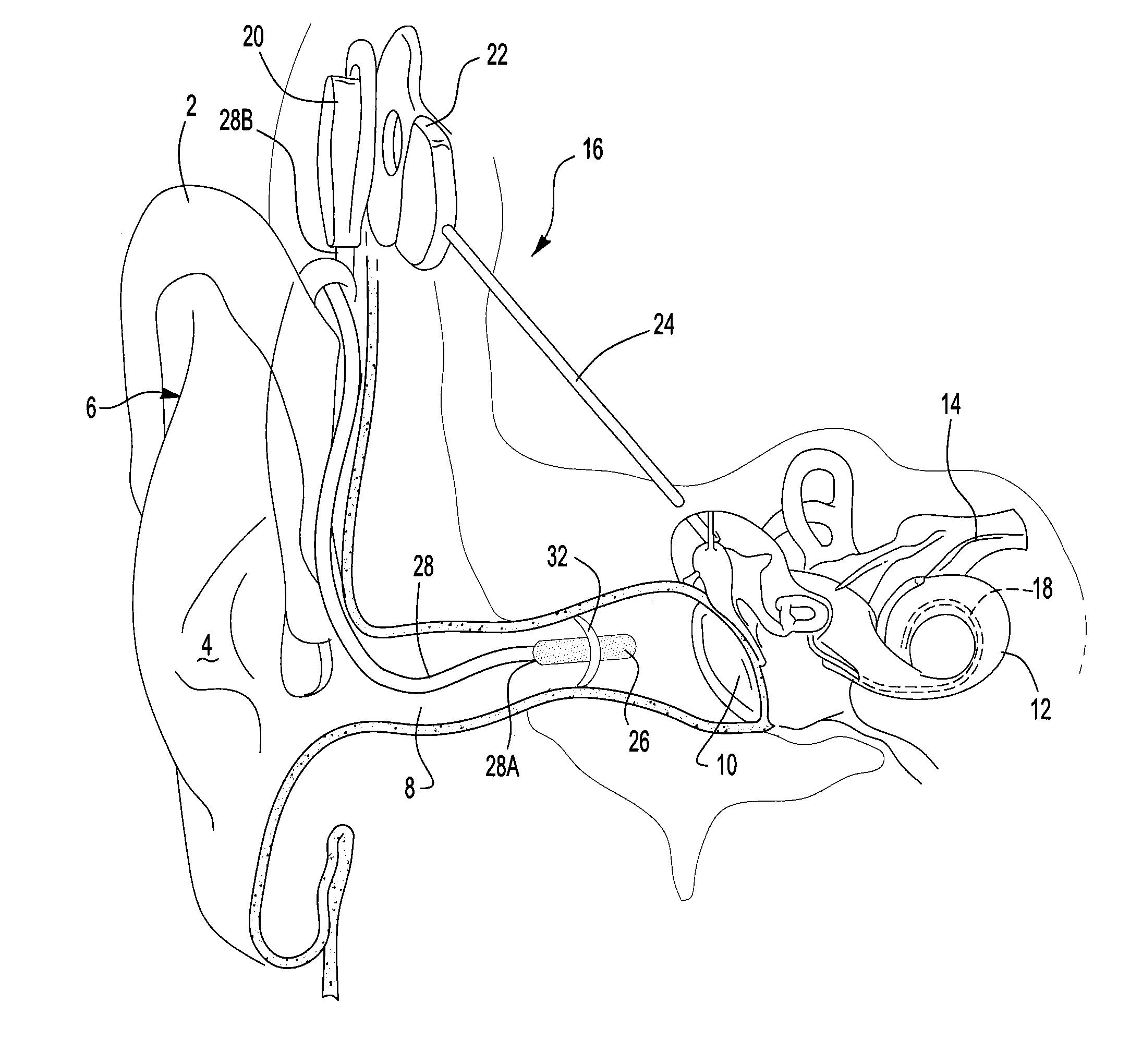
[0015]The present invention utilizes a cochlear implant with the microphone located deep within the ear canal so as to take advantage of the pinna effect and ear canal resonance effects. Such a placement of the microphone allows the sounds that the microphone picks up to be similar to those heard by a normal hearing person, thereby naturally amplifying the mid to high frequency speech sounds in relation to the low frequency background noise. This placement also eliminates environmental sounds such as wind noise, hair movement, etc. since the microphone is now concealed within the ear canal and sheltered from these. It also provides a much more effective and natural sound input to the processor, and better results for hearing speech over background noise.
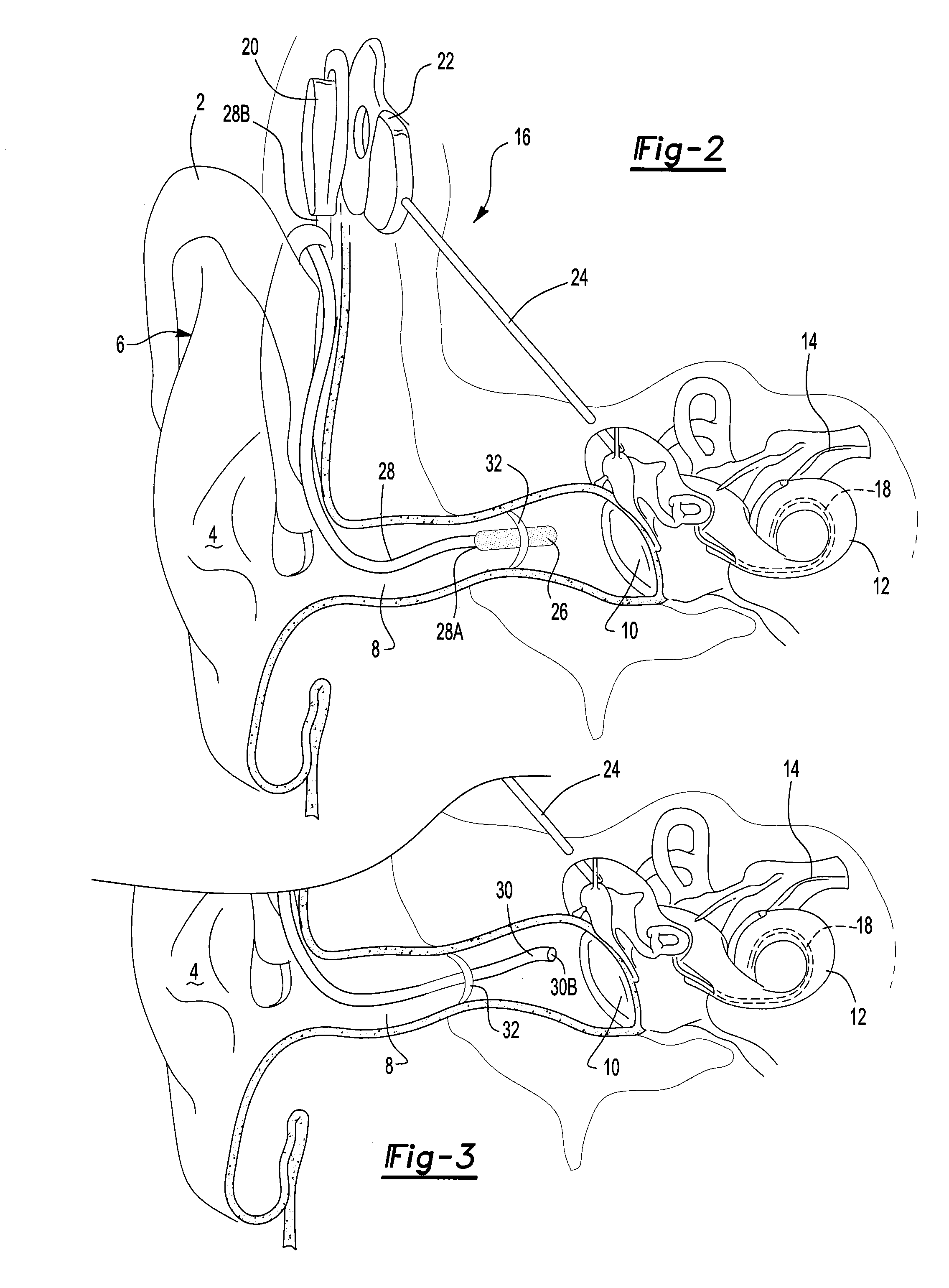
[0018]While the preferred method is to place the microphone in the canal, an alternate method is to place the microphone in the processor unit, with a flexible tube connected to it which is long enough to be formed and placed within the ear canal to gather sounds from within the ear canal and deliver them to the microphone. While there may be a slight attenuation (approximately 3-4 dB) of some frequencies within the tubing, this can be very useful for small diameter or difficult geometry ear canals for placing the point of sound pickup as close to the tympanic membrane as possible with the benefits still being far greater than the typical external microphone configuration.
[0020]It should be readily apparent to those skilled in the art that this improved device may be used on any cochlear implant configuration for patients with profound hearing loss to improve their ability to understand speech against noise backgrounds and better hearing in general.

Problems solved by technology

However, this may not be possible in some patients due to a difficult geometry of their canal and placement may be limited to 5 to 15 mm from the tympanic membrane.

Method used


Image

  • Cochlear implant
  • Cochlear implant
  • Cochlear implant

Examples


Embodiment Construction

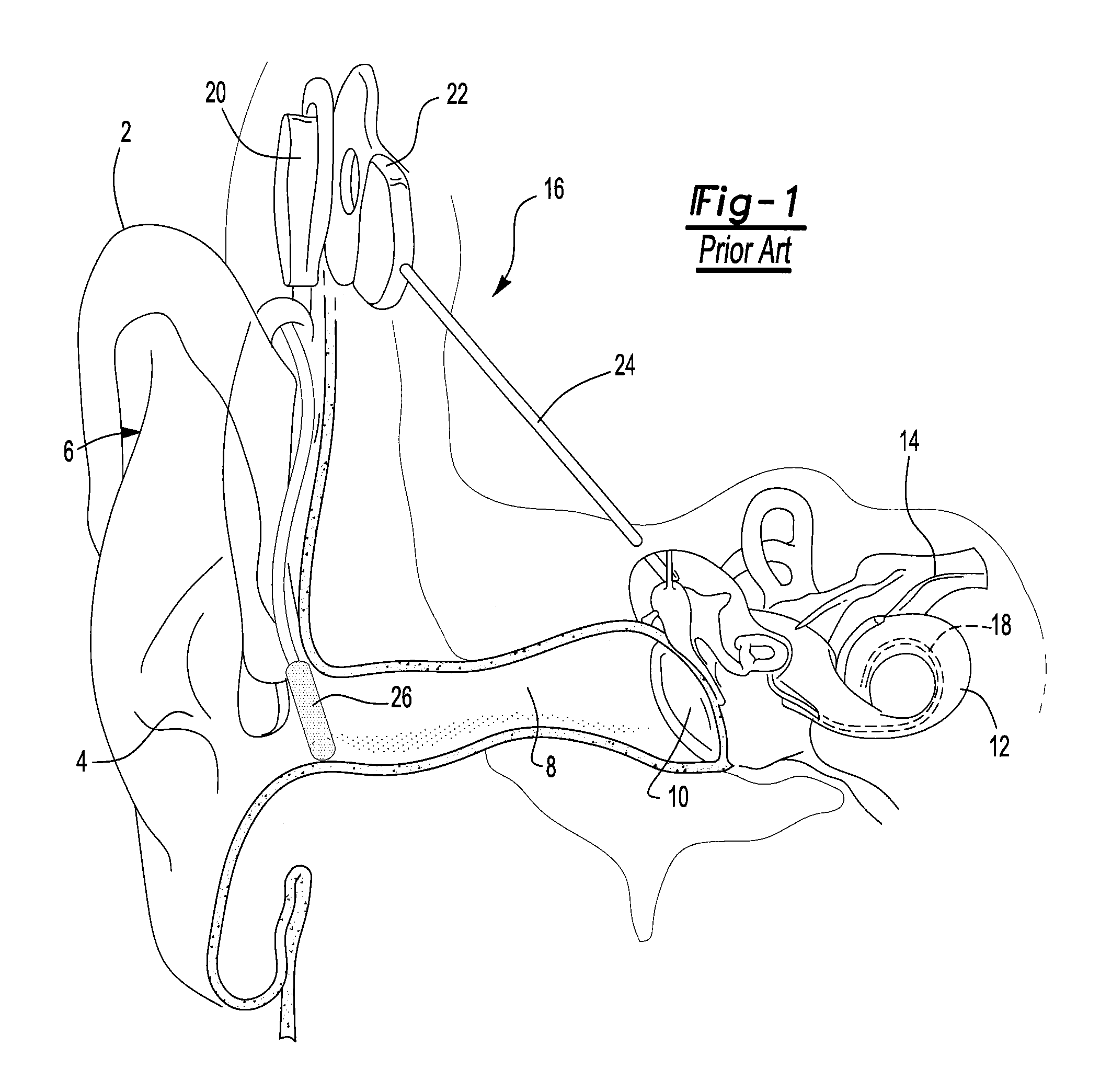
[0028]FIG. 1 shows an attempt in the prior art to improve the hearing of cochlear implant patients. Illustrated is the pinna 2, concha 4, and outer ear 6 of the human ear, as well as the ear canal 8, tympanic membrane (ear drum) 10, cochlea 12 and auditory nerve 14. Cochlear implant 16 comprising microphone 26, external processor 20, internal processor 22, connection 20 and implanted electrode 22 are also shown. The prior art has improved the hearing of cochlear implant patients by placing a microphone 26 just outside the ear canal 8 of the patient in the concha 4 of the patients a ear. As stated herein above, this provides for the use of a telephone by the cochlear implant patient. However, it does not take into account the pinna effect or ear canal resonance described above.

[0029]FIG. 2 illustrates one embodiment of the present invention, wherein a microphone 26, which may be the same as the microphone used in prior art devices, but may also be any microphone which is suitable for...


PUM


Abstract

An improved cochlear implant and method are disclosed. The present invention relates particularly to an external processing unit of a cochlear implant which processes sounds from within the ear canal of the patient. The implant comprises a microphone placed within the ear canal of the patient. The implant can alternatively comprise a hollow tube placed within the ear canal of the patient which is used to carry sound to a microphone located elsewhere. The method may comprise the steps of: providing a microphone in the ear canal, thereby improving the hearing of said hearing-impaired subject. The method may comprise the steps of: providing in the ear canal a tube that delivers sound to a microphone, thereby improving the hearing of said hearing-impaired subject.

Description

RELATED APPLICATIONS[0001]This application claims the benefit under 35 U.S.C. 119(e) of U.S. Provisional Patent Application No. 61 / 255,562, filed on Oct. 28, 2009 under the provisions of 35 U.S.C. 111(b) The contents of this provisional application are fully incorporated herein by reference.FIELD OF THE INVENTION[0002]The present invention relates to generally to the field of cochlear implants and improvements in obtaining sound quality for cochlear implant patients. The present invention relates more particularly to an external processing unit of a cochlear implant which processes sounds from within the ear canal of the patient. The present invention relates most particularly to the improved placement of the microphone used with cochlear implants to take advantage of the Pinna Effect and the Ear Canal Resonance of the human ear.BACKGROUND OF THE INVENTION[0003]Cochlear implants are used to help the profoundly deaf to hear. However, a major problem for cochlear implant users is the ...

Claims


Application Information

Patent Timeline
IPC IPC(8): A61F11/04A61N1/36
CPCA61N1/36032H04R2410/07H04R25/405A61N1/36038
Inventor SPEARMAN, MICHAEL R.SPEARMAN, BRIAN M.
Owner SPEARMAN MICHAEL R
Learn More