Systems and methods for subsea drilling

a technology of systems and methods, applied in the direction of drilling pipes, drilling well accessories, sealing/packing, etc., can solve the problems of underground blowout, accelerating the imbalance between the wellbore pressure and the formation pore pressure, etc., to improve the control of the well, improve the effect of well control, and fast regulation of annular pressur

Active Publication Date: 2011-05-05
ENHANCED DRILLING
View PDF15 Cites 57 Cited by
  • Summary
  • Abstract
  • Description
  • Claims
  • Application Information

AI Technical Summary

Benefits of technology

[0010]With this new invention, for as long as the gas is allowed to be separated from the drilling fluid / mud inside the marine drilling riser or in a separate auxiliary line / conduit and that the initial drilling fluid level is sufficiently low as indicated in FIG. 6, it will be possible to circulate out a gas kick under constant bottom hole pressure (equal to or above the formation pressure) without applying any pressure to the drilling riser or the choke line or choke at surface. This can be seen from FIG. 6. A certain amount of gas (gas 1) has entered the well bore and occupies a certain height. This has pushed the drilling fluid / mud level to a new height (level 1). As gas is circulated out under constant bottom hole pressure by pumping drilling mud down drill pipe and up the drill pipe / wellbore annulus, the gas bubble is transported higher up in the well (gas 2) where the gas will expand due to a lower pressure. This increases the volume and hence pushes the drilling fluid in the riser to a new level (level 2). As circulation progresses (gas 3) will be even higher occupying and even larger volume hence pushes mud riser level to level 3. This will continue until the gas is separated in the riser and vented to surface under atmospheric pressure. As gas is separated and heavy fluid is taken its place, the level will again fall back to the original level (level 0) or slightly higher to prevent new gas from entering the wellbore. In this way it is possible to circulate out a gas influx from deeper formations at constant bottomhole pressure without observing or applying pressure at surface or without having to close any valves or BOP elements in the system. This will greatly improve the safety of the operation and reduce the pressure requirements of risers and other equipments and can be performed dynamically without any interruption in the drilling process or pumping / circulation activity. The bottomhole pressure is simply kept constant with regulation of the liquid mud level within the marine drilling riser.

Problems solved by technology

As the formation influx normally is lighter than the drilling fluid occupying the space before, the result will be that the bottomhole pressure will get lower and lower and thereby accelerating the imbalance between the wellbore pressure and the formation pore pressure.
If this gas migration is allowed to happen without allowing the gas to expand, it could be catastrophic since the bottomhole pressure would be transferred up to surface with the gas.
The combined effect would be ever increasing pressure at the bottom of the well and to the extent that it would fracture the formation and possibly cause an underground blow-out.

Method used


Image

  • Systems and methods for subsea drilling
  • Systems and methods for subsea drilling
  • Systems and methods for subsea drilling

Examples


Embodiment Construction

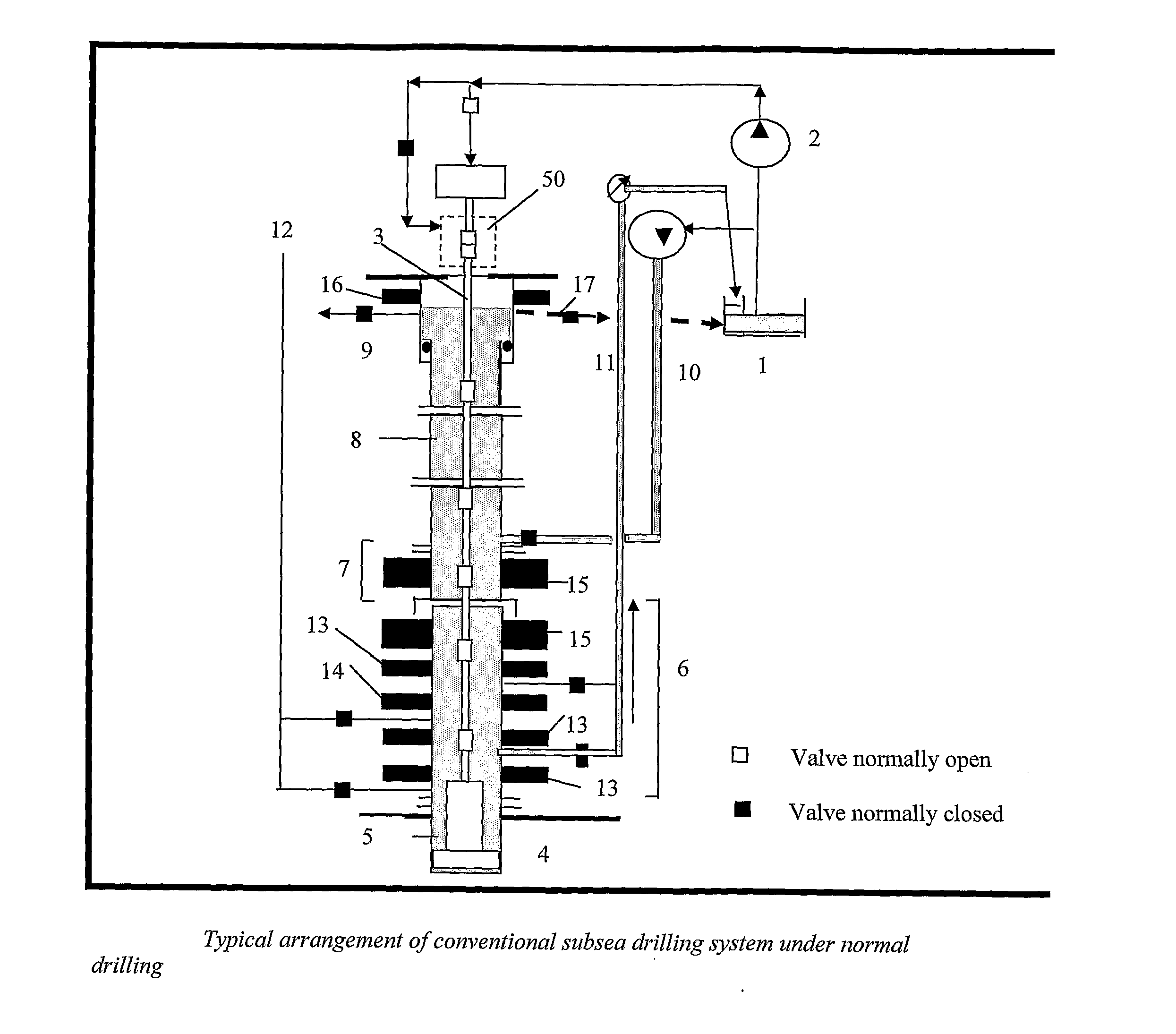
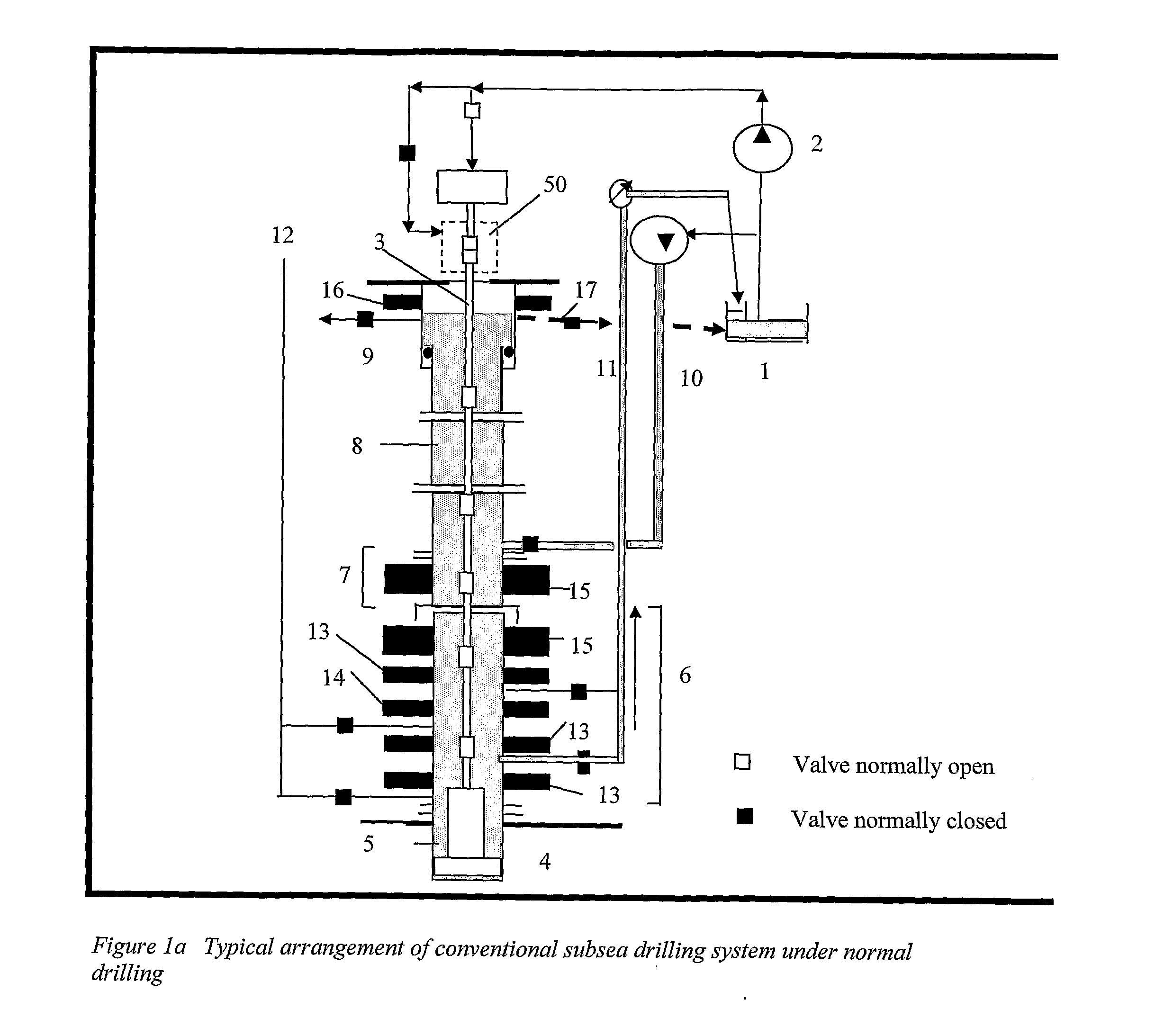
[0032]FIG. 1a illustrates a typical arrangement for subsea drilling from a floater. Mud is circulated from mud tanks (1) located on the drilling vessel, trough the rig pumps (2), drill string (3), drill bit (4) and returned up the borehole annulus (5), through the subsea BOP (6) located on the sea bed, the Lower Marine Riser Package (LMRP) (7), marine drilling riser (8), telescope joint (9) before returning to mud processing system through the flowline (17) by gravity and into the mud process plant (separating solids from drilling mud not shown) and into the mud tanks (1) for re-circulation. A booster line (10) is used for increasing the return flow and to improve drill cutting transport in the large diameter marine drilling riser. The high pressure choke line (11) and kill line (12) are used for well control procedures. The BOP , typically has variable pipe rams (13) for closing the annulus between the BOP bore and the drill string, and shear ram (14) to cut the drill string and se...


PUM


Abstract

A subsea drilling method and system for controlling the drilling fluid pressure, where drilling fluid is pumped down into the borehole through a drill string and returned back through the annulus between the drill string and the well bore. The drilling fluid pressure is controlled by draining drilling fluid out of the drilling riser (8) or BOP (6) at a level between the seabed and the sea water in order to adjust the hydrostatic head of drilling fluid. The drained drilling fluid and gas is separated in a subsea separator (28) where the gas is vented to surface through a vent line (39), and the fluid is pumped to surface via pump (40).

Description

RELATED APPLICATIONS[0001]This application is a national phase application filed under 35 USC §371 of PCT Application No. PCT / NO2009 / 000136, International filing date 6 Apr. 2009, which claims priority to NO Patent Application 2008 1668, filed 4 Apr. 2008 and NO Patent Application 2008 3453, filed 8 Aug. 2008. Each of these applications is herein incorporated by reference in their entirety for all purposes.FIELD OF THE INVENTION[0002]The present invention relates to systems, methods and arrangements for drilling subsea wells while being able to manage and regulate annular well pressures in drilling operations and in well control procedures. More specifically the invention will solve several basic problems encountered with conventional drilling and with other previous art when encountering higher than expected pressure in underground formations. These are related to pressure increases in wellbore and surface when circulating out hydrocarbon or gas influxes. The intention with the inv...

Claims


Application Information

Patent Timeline
Patent Type & Authority Applications(United States)
IPC IPC(8): E21B7/12
CPCE21B21/001E21B21/067E21B7/12E21B21/08E21B33/06E21B43/36E21B41/0007
Inventor FOSSLI, BORRE
Owner ENHANCED DRILLING
Why Eureka
Try Eureka