Control valve for a vehicle brake system, and vehicle brake sysem having such a control valve

a technology for brake systems and control valves, which is applied in the direction of braking systems, rotary clutches, fluid couplings, etc., can solve the problems of increased friction, increased extrusion, and high wear of control valves, and achieve the effect of reducing the required control pressure and improving the control quality of control valves

Inactive Publication Date: 2011-05-05
ROBERT BOSCH GMBH
View PDF9 Cites 6 Cited by
  • Summary
  • Abstract
  • Description
  • Claims
  • Application Information

AI Technical Summary

Benefits of technology

[0010]The control valve of the invention for a vehicle brake system, having the characteristics of independent claim 1, has the advantage over the prior art that it has a valve body with a seal seat and also has a sealing element coupled with a control piston. A sealing region of the sealing element cooperates with the seal seat of the valve body in order to limit an effective pressure at the second fluid connection to a predeterminable maximum pressure value, and an effective diameter of the control piston is embodied as greater than or equal to an effective diameter of the sealing element, in order to improve the control quality of the control valve and to lessen a required control pressure for actuating the control valve. The control valve of the invention has a first fluid connection, a second fluid connection, and a pressure-relieved connection to the atmosphere, in which a longitudinally movable control piston is acted upon on the pressure-relieved side with a spring force by an adjusting spring and in an outset position fully opens a fluid communication between the first fluid connection and the second fluid connection. The control valve of the invention can advantageously take on the function of an intake valve in the vehicle brake system and can additionally protect a return pump against elevated pilot pressure on the intake side.
[0012]It is especially advantageous that the control piston is coupled by a pin to the sealing element, and the control piston and the sealing element are disposed on different sides of the valve body, and the pin is guided by a flow opening of the valve body. The sealing element can for instance be slipped onto the pin and is sealed off at the rear region via a sealing lip on the pin. Furthermore, the sealing element, on the front region, can have a radial motion clearance relative to the pin. As a result, production tolerances can advantageously be compensated for, and secure closure of the valve can be ensured.
[0013]In a further feature of the control valve of the invention, the pin is connected on one end to the control piston, which is sealed off via a first seal from a first valve wall and on the other end has a collar, on which a second seal rests, which is axially prestressed via a spring element braced on the sealing element and seals off the pin from a second valve wall. The seal at the pin should be as low-friction as possible, to prevent excessive hysteresis. This is achieved by the axial prestressing of the second seal by the spring element. Thus radial prestressing of the seal, which could lead to fundamental friction in the pressureless state, can advantageously be avoided. Moreover, when a higher pressure is applied, the seal can seal with pressure reinforcement.
[0014]In a further feature of the control valve of the invention, a pressure building up at the first fluid connection moves the control piston, counter to the spring force of the adjusting spring, in the direction of the pressure-relieved connection, and the fluid communication between the first fluid connection and the second fluid connection can advantageously be reduced. At the predetermined maximum pressure value at the second fluid connection, the fluid communication between the first fluid connection and the second fluid connection is completely interrupted by a stop position of the sealing region of the sealing element in the seal seat of the valve body, and the spring force of the adjusting spring moves the control piston back out of the stop position in the direction of the outset position when the actual pressure at the second fluid connection drops below the maximum pressure value.
[0016]A vehicle brake system of the invention having the characteristics of independent claim 8 includes a master cylinder, a fluid control unit, and at least one wheel brake, in which the fluid control unit, for modulating the brake pressure of the at least one wheel brake in at least one brake circuit, includes one switchover, one intake valve, and one return pump each. The intake valve of the at least one brake circuit is advantageously embodied as a control valve of the invention as described above, which is looped into a respective section line between the corresponding return pump and the master cylinder. Thus the control valve of the invention in the vehicle brake system advantageously takes on the function of the intake valve and protects the return pump against elevated pilot pressure on the intake side. As a result of the limitation to the effective pressure on the intake side of the return pump, wear, friction, and extrusion of the seals in the return pump can be reduced, and as a result, advantageously, leakage from the return pump to the outside can also be reduced, the efficiency can be increased, and the service life of the return pump can be lengthened markedly. In a return pump embodied as a geared pump, an expensive, complex wave seal ring that withstands high pressure is avoided as well, and an inexpensive wave seal can be installed.
[0018]It is especially advantageous that the control piston of the control valve, during a suction mode of the return pump, remains in the outset position, and during a partly active state of the brake system it is subjected by the master cylinder connection to a pressure which moves the control piston in the direction of the pressure-relieved connection, counter to the spring force of the adjusting spring. Upon attainment of the maximum pressure value and the corresponding stop position, in which the sealing region of the sealing element, coupled with the control piston, provides sealing in the seal seat of the valve body, the piston completely interrupts the fluid communication between the master cylinder connection and the pipe connection. The spring force of the adjusting spring moves the control piston out of the stop position in the direction of the outset position when the actual pressure at the pipe connection drops below the maximum pressure value.

Problems solved by technology

In a version of the return pumps 15, 25 as piston pumps, this high pressure, which acts on a seal on the eccentric side of the return pumps 15, 25, can lead to very high wear, extrusion, and resultant increased leakage.
If a geared pump is used as the return pump 15, 25, then this high pressure puts stress on the wave sealing rings of the return pumps 15, 25, which can lead to increased friction and, as with the piston pump, to increased wear of the seals, and wave sealing rings that withstand high pressure are very expensive.
The control pressure for actuating the control valve 40, 40′ should therefore be relatively high, and the friction of the sealing elements can lead to increased hysteresis of the closing pressure.

Method used


Image

  • Control valve for a vehicle brake system, and vehicle brake sysem having such a control valve
  • Control valve for a vehicle brake system, and vehicle brake sysem having such a control valve
  • Control valve for a vehicle brake system, and vehicle brake sysem having such a control valve

Examples


Embodiment Construction

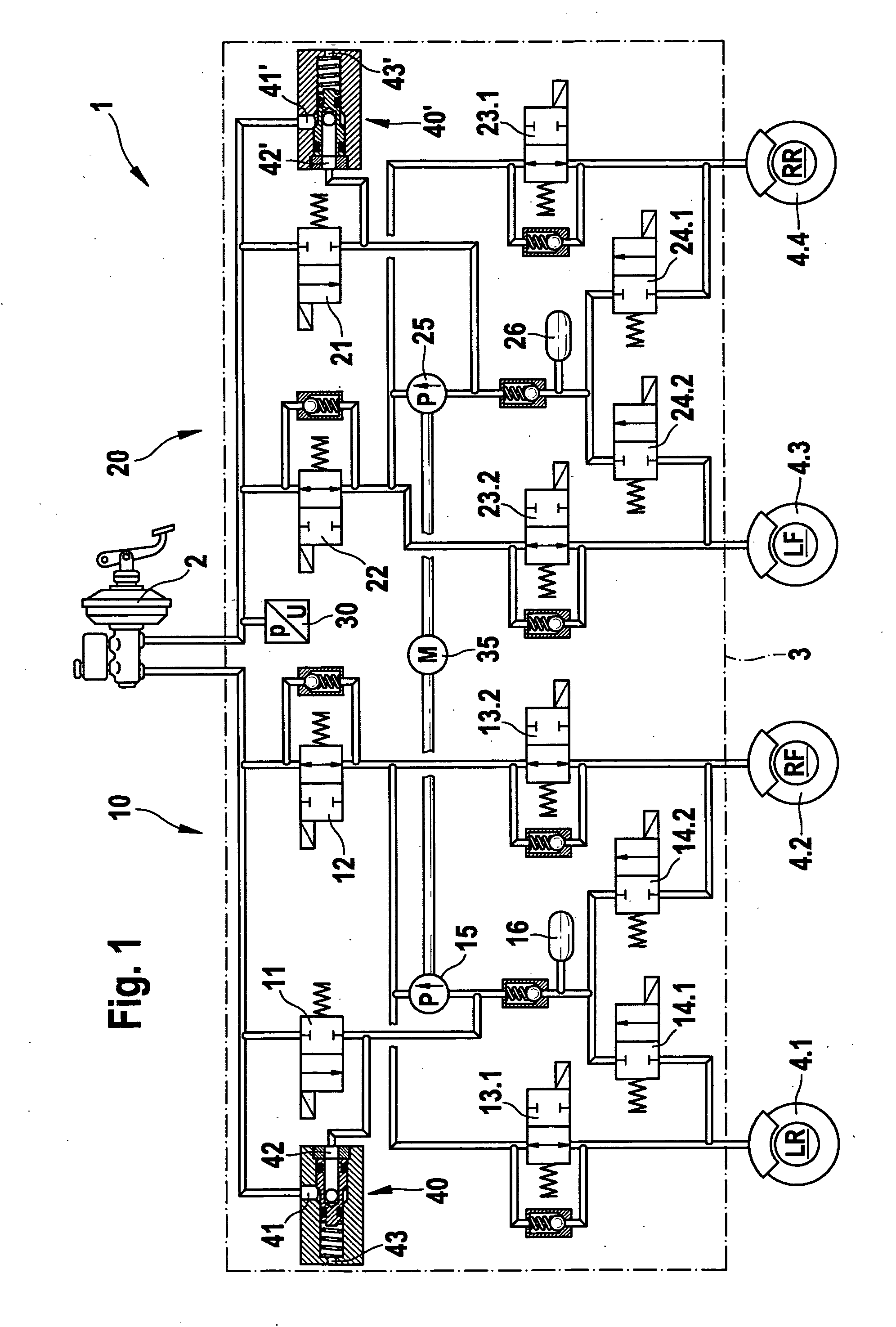
[0025]The exemplary embodiment, shown in FIG. 4, of a vehicle brake system 1′ of the invention is constructed essentially identically to the conventional vehicle brake system 1 of FIG. 1, and it includes the same components, which perform the same or analogous functions, with the addition of a first control valve 50 and a second control valve 50′. Thus the exemplary embodiment of the vehicle brake system 1′ of the invention includes a master cylinder 2, a fluid control unit 3′, indicated by dot-dashed lines, and four wheel brakes 4.1 through 4.4, which each have an associated wheel brake cylinder, not shown. Each two of the four wheel brakes 4.1 through 4.4 are assigned to one brake circuit 10′, 20′, and each brake circuit 10′, 20′ communicates with the master cylinder 2. Thus a first wheel brake 4.1, which is disposed for instance on a rear vehicle axle on the left, and a second wheel brake 4.2, which is for instance disposed on a front vehicle axle on the right, are assigned to a ...


PUM


Abstract

The invention relates to a control valve for a vehicle brake system having a first fluid connection, a second fluid connection, and a decompressed connection toward the atmosphere. An adjustment spring applies a spring force to a control piston moving in longitudinal direction on the decompressed side, the control piston completely releasing a fluid connection between the first fluid connection and the second fluid connection in an initial position, and to a corresponding vehicle brake system having such a control valve. According to the invention the control valve includes a valve body having a seal seat and a sealing element coupled to a control piston. A sealing region of the sealing element interacts with the seal seat of the valve body in order to limit an effective pressure present on the second fluid connection to a predetermined maximum pressure value. The effective diameter of the control piston is greater than or equal to an effective diameter of the sealing element.

Description

PRIOR ART[0001]The invention is based on a control valve for a vehicle brake system as generically defined by the preamble to independent claim 1.[0002]From the prior art, vehicle brake systems are known which include various safety systems, such as an anti-lock system (ABS), an electronic stability program (ESP), and so forth, and which perform various safety functions, such as an anti-lock function, traction control (TC), and so forth. FIG. 1 shows a vehicle brake system with which various safety functions can be performed.[0003]As can be seen from FIG. 1, a conventional vehicle brake system 1 has a master cylinder 2, a fluid control unit 3, indicated by dot-dashed lines, and four wheel brakes 4.1 through 4.4, which each have an associated wheel brake cylinder, not shown. Each two of the four wheel brakes 4.1 through 4.4 are assigned to one brake circuit 10, 20, and each brake circuit 10, 20 communicates with the master cylinder 2. Thus a first wheel brake 4.1, which is disposed f...

Claims


Application Information

Patent Timeline
Patent Type & Authority Applications(United States)
IPC IPC(8): B60T8/34B60T13/16F15B7/10F15B7/00
CPCB60T8/341F16K31/1223F15B13/025B60T8/4872
Inventor SCHEPP, RENEALAZE, NORBERT
Owner ROBERT BOSCH GMBH
Why Eureka
Try Eureka