Spark plug having pressure sensor

a technology of pressure sensor and spark plug, which is applied in the direction of engine ignition, structural/machine measurement, instruments, etc., can solve the problems of high risk of breakage, reduced thickness of ceramic body, and high risk of breakdown on electrical loading by ignition voltage, etc., and achieves the effect of increasing mechanical strength

Inactive Publication Date: 2011-05-05
KISTLER HLDG AG
View PDF1 Cites 12 Cited by
  • Summary
  • Abstract
  • Description
  • Claims
  • Application Information

AI Technical Summary

Benefits of technology

[0014]The object of the present invention is to specify a spark plug of the above-described type with regard to its basic design, which has increased mechanical strength, while at the same time shifting the ceramic body in the direction of the central axis of the housing.
[0017]Because the diameter in this region does not decrease abruptly but continuously over this region, bending strength is increased and the risk of the ceramic body breaking is greatly reduced. The structurally induced potential breakage point of the prior art owing to the abruptly reduced wall thickness of the ceramic body behind the stop is in particular eliminated.
[0018]In addition, the greater outer diameter of the ceramic body which is achieved in this manner means that the wall thickness of the latter is increased towards the rear, which has a direct effect on greater breakdown resistance. The insulation thickness of the ceramic body at each point can be optimised to the structural conditions by the essentially continuous reduction in the outer diameter. This means that a central cutout for an interference suppression resistor can be arranged in the rear region, it being possible to retain the necessary wall thickness of the ceramic body for the breakdown resistance.

Problems solved by technology

This has the disadvantage that the point of tapering is a very weak point in the ceramic body, which is exposed to a high risk of breakage on mechanical loading.
The wall thickness of the ceramic body is also reduced by the reduced outer diameter, which results in a high risk of breakdown on electrical loading by ignition voltage.
Such spark plugs are insufficient for use.
The problems arise from the interaction of different circumstances:
A shift of the axis of the ceramic body is disadvantageous owing to the changed ignition conditions in the combustion chamber.
The ceramic body is additionally exposed to high mechanical stresses during installation in the engine and during use.
For example, a lateral force during the rear connection of the spark plug, caused by the application of force by a mechanic or by severe vibrations during use, can cause a breakage of the ceramic body in the region of the thread between the rear sealing face as far as the front clamping shoulder.
This region is particularly at risk, because it must be thin in the thread region and is clamped between the clamping shoulder and the stop.
These generally have the disadvantage that a sensor cable projects out of the spark plug.
The disadvantage is that the cable cannot be replaced separately.
A disadvantage of such a spark plug 1 according to FIG. 1 is the thinness of the ceramic in the part of the ceramic body 6 between the front clamping shoulder 8 and the step 20, and the associated susceptibility to breakage of the ceramic body on tangential application of force in the region of the connection 17, as a consequence of the reduced outer diameter DK, because the pressure sensor 4 and / or the contact necessary for it must have space as well.
The thinness also increases the risk of breakdown.
The risk of breakage is particularly increased if the ceramic body projects out of the housing at the rear.
A great disadvantage of such a spark plug 1 according to FIG. 1 is the high risk of breakage at the step 20.
This point is exposed to high stress during severe vibrations.
Even a small hairline crack greatly increases the risk of breakdown at this point.
This spark plug 1 according to FIG. 1 is thus not appropriate for any normal situation.

Method used


Image

  • Spark plug having pressure sensor
  • Spark plug having pressure sensor
  • Spark plug having pressure sensor

Examples


Embodiment Construction

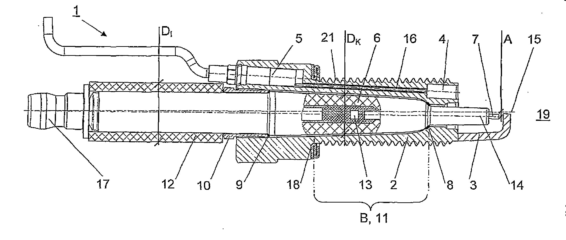
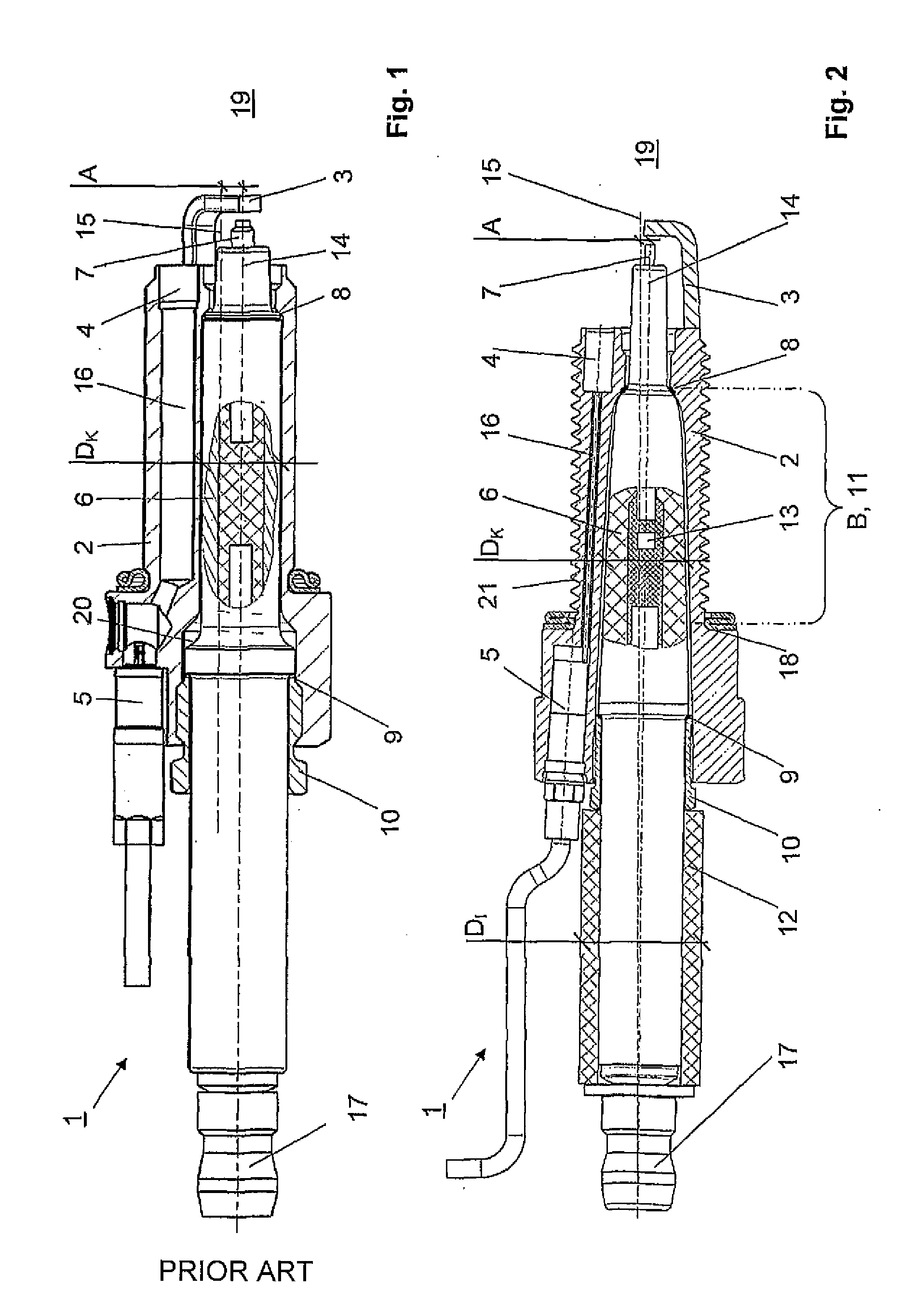
[0024]FIG. 2 shows a schematic sectional illustration of a spark plug 1 according to the invention. It likewise comprises a housing 2 with a thread 21 and a sealing face towards the engine 18, an earth electrode 3 at the front and, arranged next to the latter, a pressure sensor 4 with a sensor connector 5 and a ceramic body 6 with a central electrode 7. The ceramic body 6 in turn has a front clamping shoulder 8 and a rear stop 9, by means of which the ceramic body 6 can be clamped in the housing 2 with the aid of a screw connection 10. As an alternative, it is also possible for a sensor connector 5 to be attached to the housing 2, in which case only a cable guide leads out of the housing 2.

[0025]In preferred embodiments the sensor is installed in the front region of the spark plug, preferably frontally on the combustion chamber side. This is a structural necessity particularly if the thread is an M14 thread or smaller.

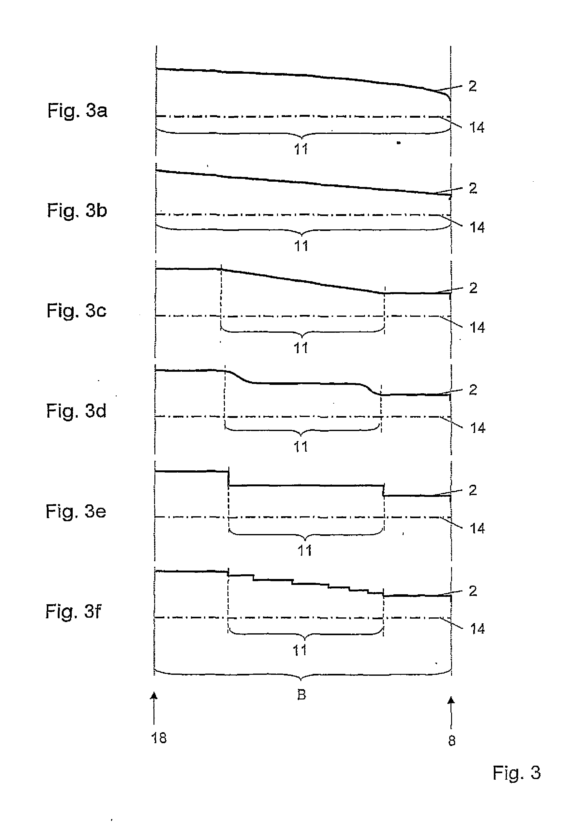
[0026]In contrast to the prior art, the outer diameter DK of the ...


PUM


Abstract

A spark plug is intended for combustion engines and comprises a metal housing having a ground electrode disposed at the front and a thread having a rear sealing surface for installation in the combustion engine. The spark plug in particular includes a pressure sensor disposed laterally in the housing for determining a combustion chamber pressure and a ceramic body having a center electrode. The ceramic body is disposed in the housing next to the pressure sensor and acting as an electric insulator. As viewed from the combustion chamber, the ceramic body defines a front clamping shoulder and a rear stop for clamping the ceramic body into the housing. The outside diameter of the ceramic body gradually decreases in the region of the thread located between the rear sealing surface and the front clamping shoulder.

Description

CROSS-REFERENCE TO RELATED APPLICATIONS[0001]This application claims priority to International Application Serial No. PCT / CH2009 / 000230 filed Jul. 2, 2009, which claims priority to Swiss Application No. CH 1035 / 08 filed Jul. 2, 2008.TECHNICAL FIELD[0002]The invention relates to a spark plug, the basic design of which is intended for internal combustion engines, comprising a metallic housing with an earth electrode arranged at the front and a thread with a rear sealing face for installation in the internal combustion engine, a pressure sensor arranged laterally in the housing for determining a combustion chamber pressure, a ceramic body with a central electrode, which sensor is arranged next to the pressure sensor in the housing and acts as an electrical insulator, wherein the ceramic body, as viewed from the combustion chamber, has front clamping shoulders and a rear stop for clamping the ceramic body in the housing.BACKGROUND[0003]Spark plugs of this type are already known. To acco...

Claims


Application Information

Patent Timeline
Patent Type & Authority Applications(United States)
IPC IPC(8): H01T13/20G01M15/08
CPCF02D35/023G01L23/222F02P13/00
Inventor GLASER, JOSEFLEUPRECHT, GERNOT
Owner KISTLER HLDG AG
Why Eureka
Try Eureka