
System and Method For Panoramic Image Stitching

a panoramic image and stitching technology, applied in the field of automatic identification systems, can solve problems such as difficult processing, and achieve the effects of more quickly processing information, more quickly performing image processing of targets, and more quickly performing image processing

Active Publication Date: 2011-05-05
NOVANTA CORP
View PDF15 Cites 57 Cited by
  • Summary
  • Abstract
  • Description
  • Claims
  • Application Information

AI Technical Summary

Benefits of technology

[0006]It is therefore a principal object and advantage of the present invention to provide a system and method for preparing a single panoramic image of a target for autoidentification processing.
[0007]It is another object and advantage of the present invention to provide a system and method for more quickly performing image processing of targets that are in motion.
[0008]It is a further object and advantage of the present invention to provide a system and method for more quickly performing image processing of targets having information encoded or placed on multiples sides.
[0009]It is an additional object and advantage of the present invention to provide a system and method for more quickly processing information about the targets themselves.
[0010]In accordance with the foregoing objects and advantages, the present invention provides a system for capturing images of a target, such as a test tube, that is presented in front of an optical imager and rotated 360 degrees. While the target is rotating, the imager of the system captures a series of images which are then stitched together to form a panoramic image of the target. The panoramic image may then be processed to decode any barcode code information placed on the target, capture other information placed on the target, or obtain information about the target or the contents thereof.BRIEF DESCRIPTION OF THE SEVERAL VIEWS OF THE DRAWING(S)

Problems solved by technology

When a target, such as a test tube, contains several labels, processing may become very difficult as images need to be taken from multiple perspectives.

Method used


Image

  • System and Method For Panoramic Image Stitching
  • System and Method For Panoramic Image Stitching
  • System and Method For Panoramic Image Stitching

Examples


Embodiment Construction

invention.

[0016]FIG. 5 is a series of images to be formed into a panoramic image according to the present invention.

[0017]FIG. 6 is a series of images formed into a panoramic image according to the present invention.

[0018]FIG. 7 is a series of images illustrating a barcode decoding and fluid level detection process according to the present invention.

DETAILED DESCRIPTION OF THE INVENTION

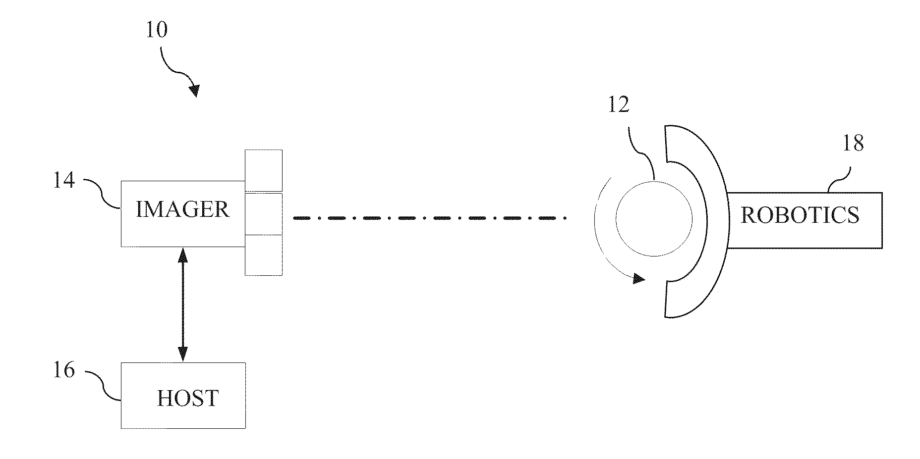
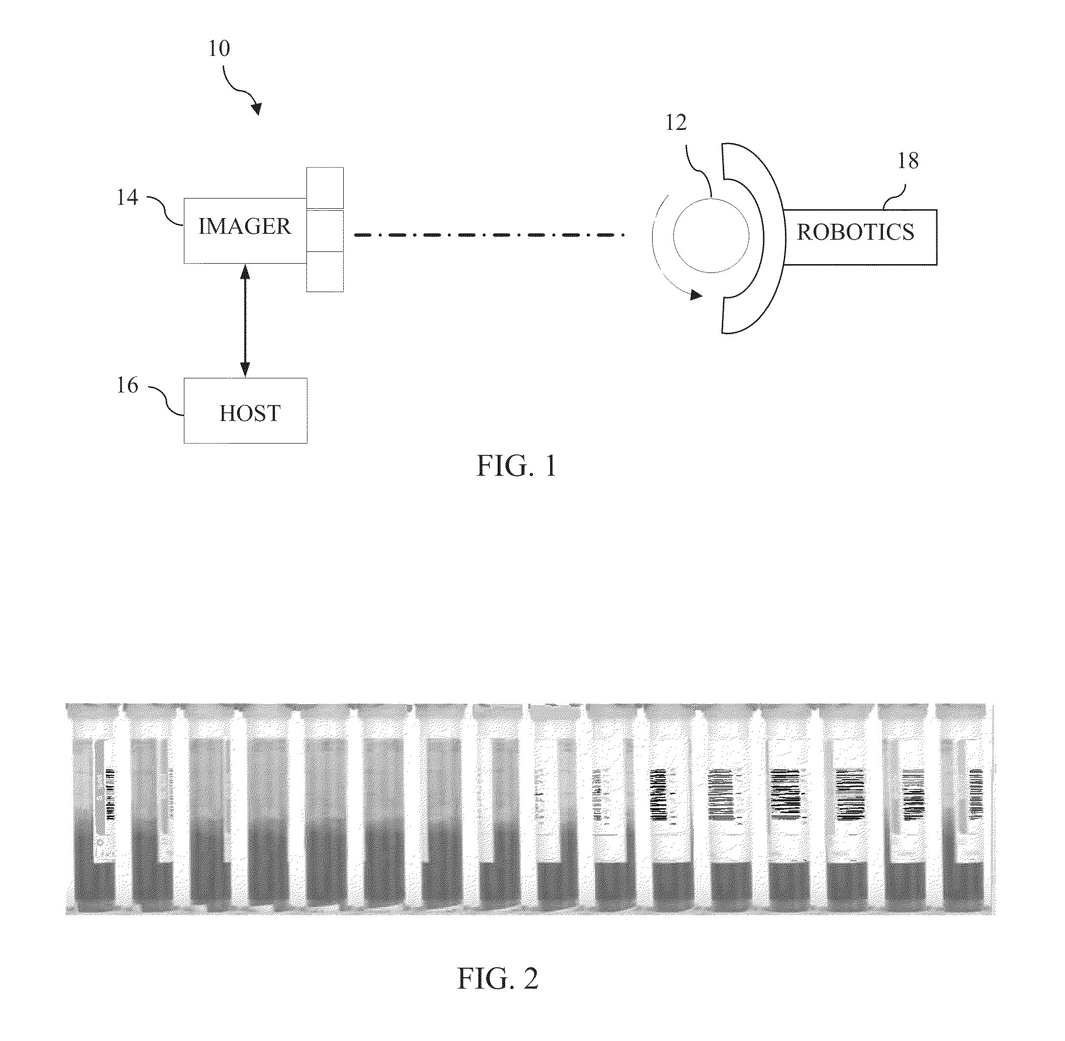
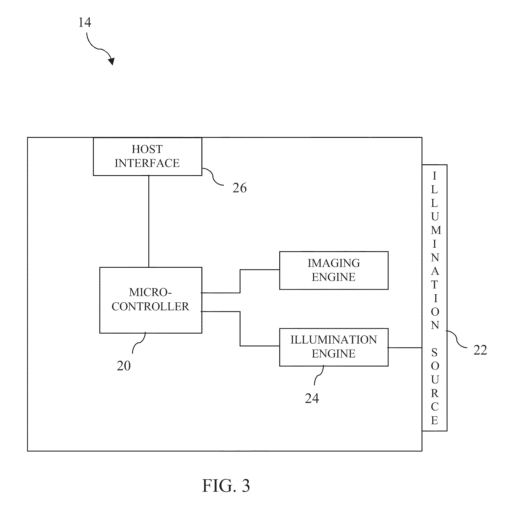
[0019]Referring now to the drawings, wherein like reference numerals refer to like parts throughout, there is seen in FIG. 1 a storage retrieval system 10, such as an in vitro patient diagnostic test tube system, that is responsible for handling a plurality of targets, referred herein more specifically as patient sample test tubes 12. Tubes 12 are referred to herein can be any form of vessel, such as beakers, bottles, vials, etc., and may contain any variety of fluids (blood, urine, saliva, etc.) for robotic processeding by system 10. In particular, tubes 12 are presented to an optical imager 14, such...


PUM


Abstract

A system for capturing images of a target, such as a test tube, that is presented in front of an optical imager and rotated 360 degrees. The imager of the system captures a series of images which are then stitched together to form a panoramic image of the target. The panoramic image may then be processed to decode any barcode code information placed on the target, capture other information placed on the target, or obtain information about the target or the contents thereof.

Description

BACKGROUND OF THE INVENTION[0001]1. Field of the Invention[0002]The present invention relates to autoidentification systems and, more specifically, to a system and method for preparing panoramic optical images for autoidentification decoding processes.[0003]2. Description of the Related Art[0004]Machine vision plays an important role in automated and robotic systems, such as assembly line manufacturing, quality control inspection, and sample processing. Conventional systems are generally comprised of an optical imager, such as a charged coupled device (CCD) or similar device using digital imaging technology, which is positioned to capture images of objects that pass in front of it. In low-light or enclosed applications, machine vision systems may include an illumination source, such as a bank of light emitting diodes (LEDs), positioned proximately to the imager. The images are subsequently processed to decode information contained in the resulting two-dimensional image, such as 1D l...

Claims


Application Information

Patent Timeline
Patent Type & Authority Applications(United States)
IPC IPC(8): H04N7/00
CPCG01N2035/00752G01N2035/1018G06T2200/32G06T3/4038G01N2035/1025
Inventor CHEN, MOGODICI, DANIEL FRANCIS
Owner NOVANTA CORP
Learn More