Docking station with extended USB interface for wireless electro-optical reader

a wireless electro-optical reader and extended technology, applied in the direction of instruments, electrical apparatus casings/cabinets/drawers, instruments, etc., can solve the problems of increasing the cost of such docking stations, affecting the operation of the device, so as to achieve the effect of less expensive and better access to the usb socket interfa

Inactive Publication Date: 2011-05-05
SYMBOL TECH INC
View PDF5 Cites 16 Cited by
  • Summary
  • Abstract
  • Description
  • Claims
  • Application Information

AI Technical Summary

Benefits of technology

[0010]Hence, in accordance with this invention, the docking station is less expensive than heretofore, because RF transceiver circuitry and power recharging circuitry are no longer required to be accommodated therein. Also, better access to the USB socket interface is obtained, because the USB socket interface is readily accessible at the docking station, and not the back of the host. An operator need no longer stick his or her head and hand to the back of the host to gain access to the USB socket interface for insertion and pulling out a USB plug interface on a USB peripheral.

Problems solved by technology

As advantageous as such docking stations are, they are relatively expensive to manufacture, because they typically require relatively costly RF transceiver circuitry and power recharging circuitry to be accommodated therein, typically on one or more printed circuit boards (PCBs).
The cost of such docking stations increases when a particular venue has a multitude of such docking stations, one for each reader.
If a USB peripheral is desired to be installed, then an operator must stick his or her head and hand to the back of the host to gain access to the USB socket interface for insertion and pulling out a USB plug interface on the peripheral, thereby resulting in much inconvenience.

Method used


Image

  • Docking station with extended USB interface for wireless electro-optical reader
  • Docking station with extended USB interface for wireless electro-optical reader
  • Docking station with extended USB interface for wireless electro-optical reader

Examples


Embodiment Construction

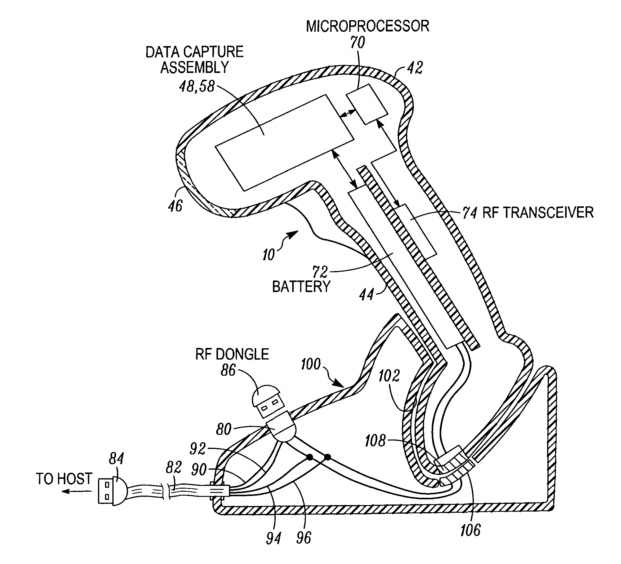
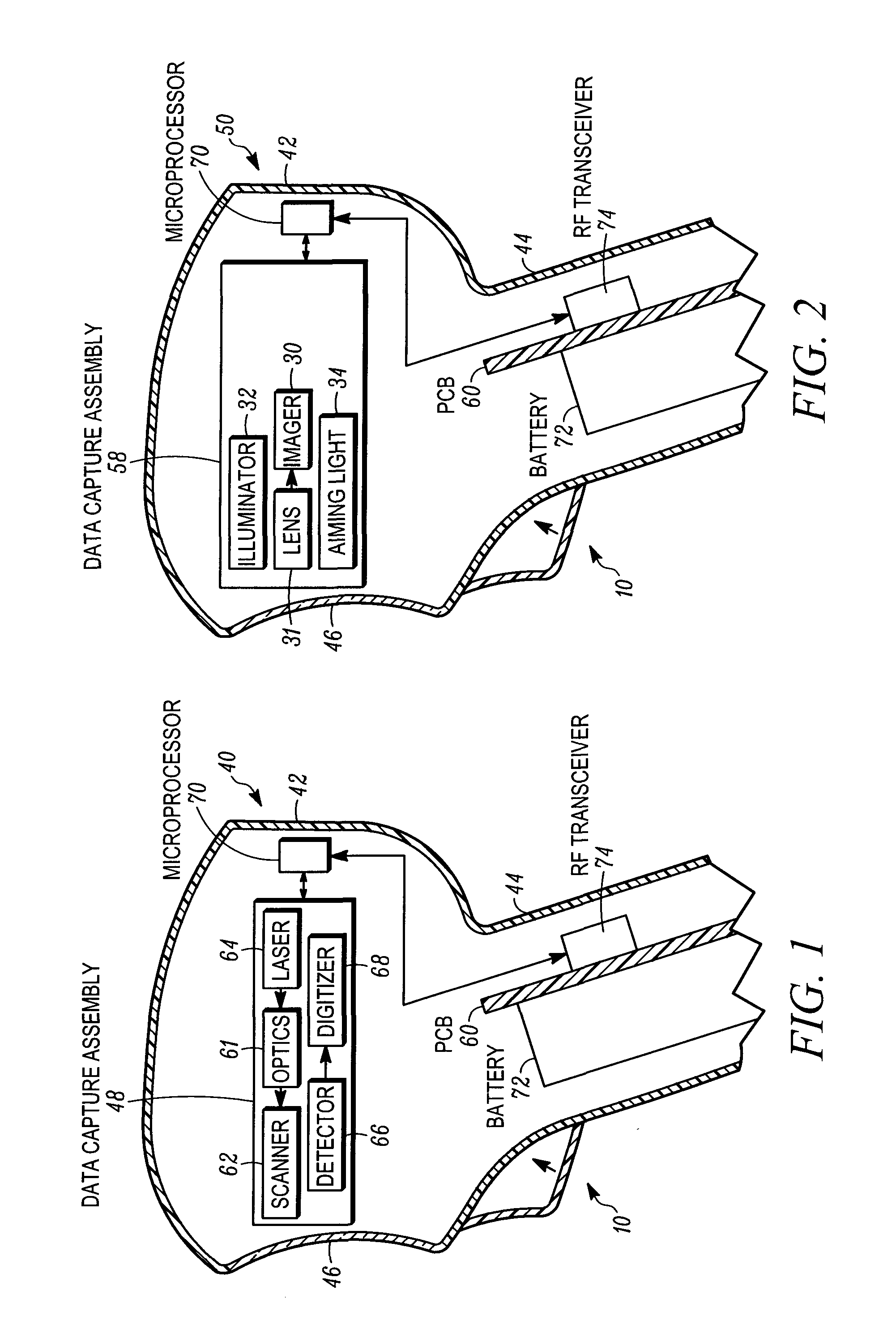
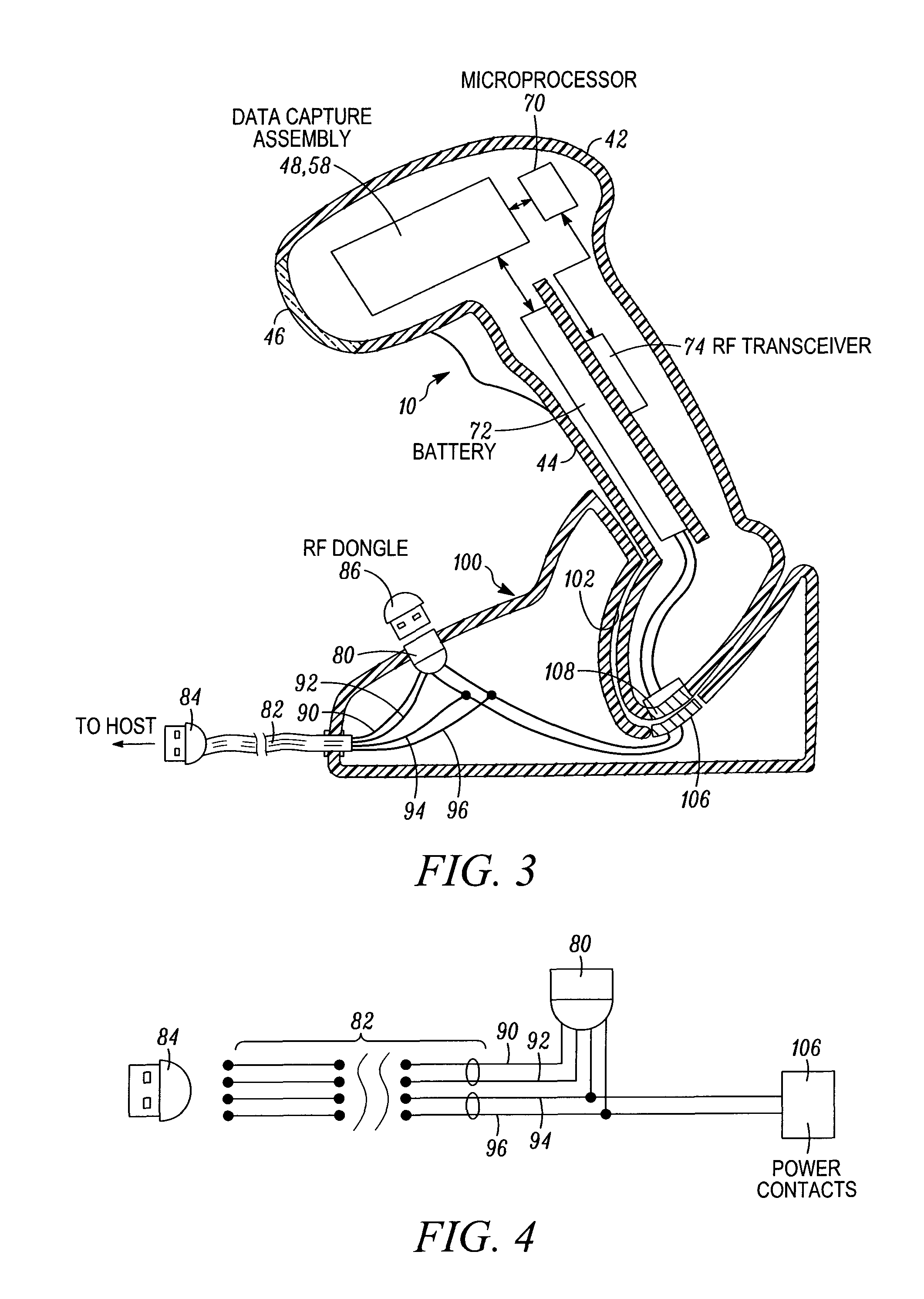
[0018]FIG. 1 depicts a moving laser beam reader 40 for electro-optically reading a target such as a coded symbol, that may use, and benefit from, the present invention. The beam reader 40 includes a scanner 62 in a portable, handheld housing 42 having a handle 44 on which a trigger 10 for initiating reading is mounted. The scanner 62 is operative for scanning an outgoing laser beam from a laser 64 and / or a field of view of a light detector or photodiode 66 in a scan pattern, typically comprised of one or more scan lines, multiple times per second, for example, one-hundred times per second, through a window 46 across the symbol for reflection or scattering therefrom as return light detected by the photodiode 66 during reading. The beam reader 40 also includes a focusing lens assembly or optics 61 for optically modifying the outgoing laser beam to have a large depth of field, and a digitizer 68 for converting an electrical analog signal generated by the detector 66 from the return lig...


PUM

PropertyMeasurementUnit
timeaaaaaaaaaa
currentaaaaaaaaaa
currentaaaaaaaaaa

Abstract

A docking station supports a portable electro-optical reader, such as a moving laser beam reader or an imaging reader. The docking station includes a universal serial bus (USB) socket interface supported by the docking station, and a USB extension cable connected to the USB socket interface. The USB cable extends away from the docking station and terminates in a USB plug interface. A radio frequency (RF) peripheral is inserted into the USB socket interface, for wireless RF communication with the reader when the reader is not supported on the docking station. The USB cable is connected to power contacts on the docking station for mating with charging contacts connected to a rechargeable battery in the reader to charge the battery when the reader is supported by the docking station.

Description

DESCRIPTION OF THE RELATED ART[0001]Moving laser beam readers or laser scanners have long been used to electro-optically read one- and two-dimensional bar code symbols. The moving laser beam reader generally includes a housing, a laser for emitting a laser beam, a focusing lens assembly for focusing the laser beam to form a beam spot having a certain size at a focal plane in a range of working distances relative to the housing, a scan component for repetitively scanning the beam spot across a target symbol in a scan pattern, for example, a scan line or a series of scan lines, across the symbol multiple times per second, a photodetector for detecting light reflected and / or scattered from the symbol and for converting the detected light into an analog electrical signal, and signal processing circuitry including a digitizer for digitizing the analog signal and a microprocessor for decoding the digitized signal based upon a specific symbology used for the symbol. The decoded signal is t...

Claims


Application Information

Patent Timeline
Patent Type & Authority Applications(United States)
IPC IPC(8): G06F1/16G06K7/10B23P11/00
CPCG06F1/1632Y10T29/49826G06K17/0022G06K7/10881
Inventor BROCK, CHRISTOPHER WARREN
Owner SYMBOL TECH INC
Why Eureka
Try Eureka