Floor tile

a technology of floor tiles and injection molding, which is applied in the field of floor tiles, can solve the problems of increasing the cost of manufacturing the resultant tile, and the difficulty of manufacturing an injection molding plastic tile with two or more perceptible colors per tile, and achieves the effect of convenient, rapid and relatively inexpensive creation

Active Publication Date: 2011-05-05
MACNEIL IP
View PDF80 Cites 39 Cited by
  • Summary
  • Abstract
  • Description
  • Claims
  • Application Information

AI Technical Summary

Benefits of technology

[0016]The present invention provides a first technical advantage in that a plastic tile can be created out of two polymer compounds of different strengths, durometer measurements and / or contrasting colors. As preferably fabricated in a two-shot injection molding process, flashing from the second polymer compound is avoided, permitting sharply defined features made of the second polymer compound on the tile's upper surface, which then will be aesthetically pleasing and commercially acceptable. If the first and second polymer compounds are selected for good adherence to each other, the tile may further have weight-supporting members on its lower surface that can support loads of the sort which can be imposed by motor vehicles, but yet provide nonslip characteristics. The nonslip pads on the upper surface and the nonslip members on the lower surface can be conveniently, rapidly and relatively inexpensively created in the second shot of the injection molding process. The latches and loops of the invention provide a further technical advantage in their ability to tightly hold together joined adjacent tiles under a lateral biasing force.

Problems solved by technology

But manufacturing an injection-molded plastic tile that has two or more perceptible colors per tile is more difficult and to date no such tile has been provided that has proven to be acceptable to the consumer.
But it is believed that the separate molding of these inserts, flash removal from them and physical insertion of them into respective receiving holes in the plastic tile substrate is time-consumptive and greatly increases the cost of manufacture of the resultant tile.

Method used


Image

  • Floor tile
  • Floor tile
  • Floor tile

Examples


Embodiment Construction

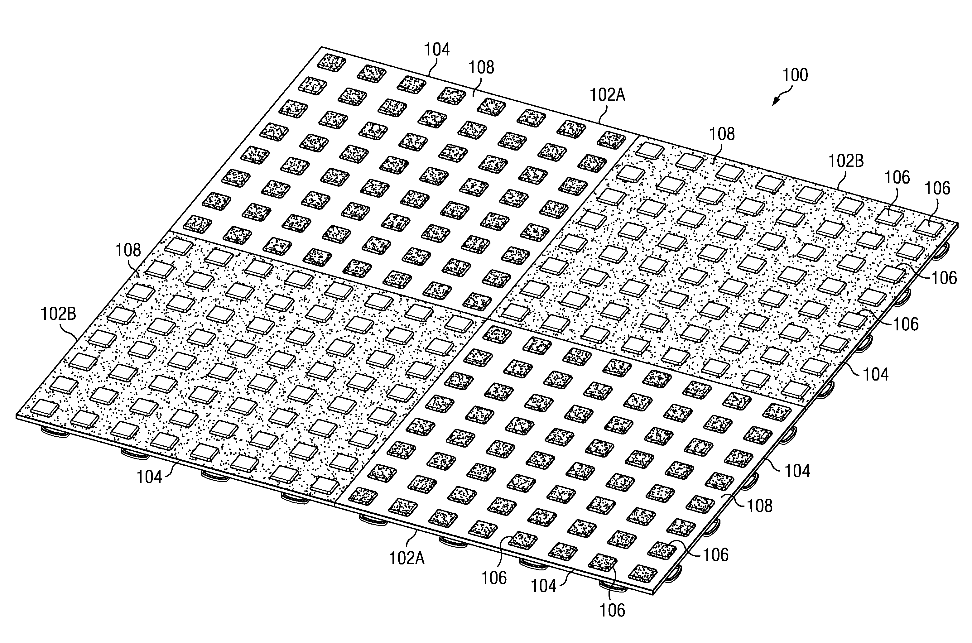
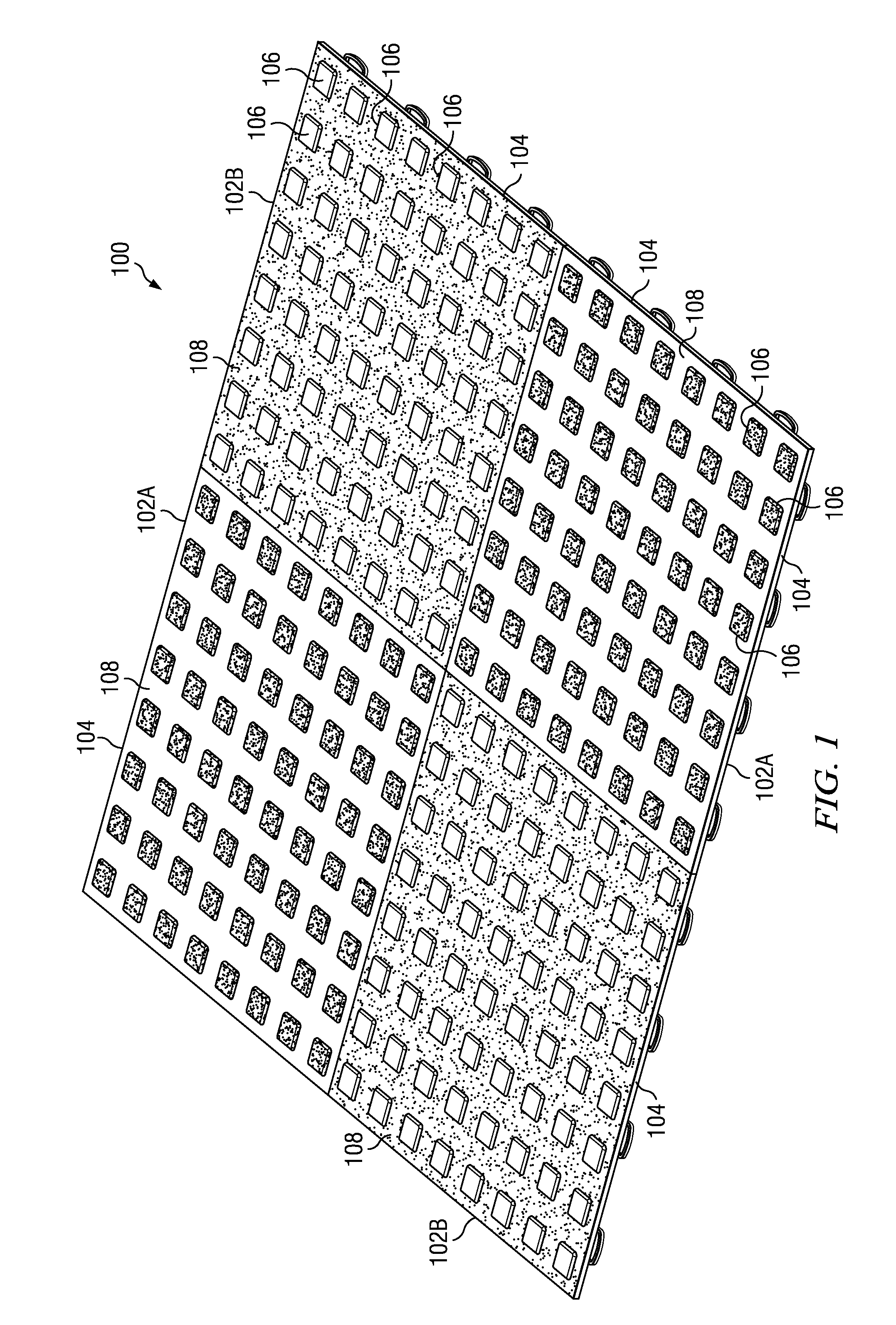
[0038]Modular floor tiles according to the invention can be used to form a flooring surface, a representative portion 100 of which is shown in FIG. 1. In this illustrated embodiment, the flooring surface 100 is made up of tiles 102, including first floor tiles 102A and second floor tiles 102B, which are identical except as to color. The floor tiles 102A each have a body 104 injection-molded from a first polymer compound, preferably comprising a polymer which is relatively rigid when solidified and which can be selected from the group consisting of polyolefins including polypropylene and high molecular weight polyethylene, rigid thermoplastic polyurethane (TPU), acrylonitrile butadiene styrene (ABS) and rigid polyvinyl chloride (PVC). The first polymer compound may further include a filler such as talc to aid in achieving surface flatness, and a pigment. Floor tiles 102B have bodies 104 which preferably are made of a polymer compound identical to that forming bodies 104 of tiles 102A...


PUM

PropertyMeasurementUnit
lengthaaaaaaaaaa
lengthaaaaaaaaaa
lengthaaaaaaaaaa

Abstract

A modular plastic floor tile has a body of a first polymer compound and features overmolded onto the body from a second polymer compound. The compounds may be different from each other in hardness and/or color. The features may include raised pads on the upper surface and/or skins on support member cores downwardly depending from the tile lower surface. The pads on the upper surface may be injection-molded from the lower surface through through-holes. Lateral edges of the tile are provided with latches which fit into loops with an interference fit. The loops flex in order to impose a compressive force on mating tile edges. The tile may have an overmolded peripheral seal.

Description

BACKGROUND OF THE INVENTION[0001]Conventional modular injection-molded tiles are known in the art for laying across upper surfaces of garage floors, sports surfaces, outdoor surfaces and other substrates. These tiles typically are twelve to thirteen inches square and can be manually assembled and disassembled. A common feature of these tiles is their ability to be snapped together, with few or no tools, using male and female connectors molded into each tile for the purpose.[0002]Conventional single tiles are molded to be a single, uniform color such as all-black or all-red. The consumer typically can choose different tiles in different colors. The consumer or contractor will often choose two or more colors for a particular floor, for assembly into an aesthetically pleasing pattern. But manufacturing an injection-molded plastic tile that has two or more perceptible colors per tile is more difficult and to date no such tile has been provided that has proven to be acceptable to the con...

Claims


Application Information

Patent Timeline
Patent Type & Authority Applications(United States)
IPC IPC(8): B32B3/10B32B7/02B32B3/02B32B3/30B32B7/04B28B7/22E04F15/022
CPCE01C5/226Y10T428/24347E01C2201/12E01C2201/16E01C5/20Y10T428/24339Y10T428/24331Y10T428/24802Y10T428/24777Y10T428/24983Y10T428/24612Y10T428/24942Y10T428/24322Y10T428/24752E01C13/045E04F15/02194E04F15/105B29C45/14B32B7/04B32B3/266B29C45/16
Inventor MASANEK, JR., FREDERICK W.IVERSON, DAVID S.THOM, ALLAN R.
Owner MACNEIL IP
Why Eureka
Try Eureka