Eureka AIR delivers breakthrough ideas for toughest innovation challenges, trusted by R&D personnel around the world.

Data transfer apparatus

Inactive Publication Date: 2011-05-05
SONY CORP
View PDF6 Cites 6 Cited by
  • Summary
  • Abstract
  • Description
  • Claims
  • Application Information

AI Technical Summary

Benefits of technology

In light of the foregoing, it is desirable to provide a novel and improved data transfer apparatus, with an inexpensive configuration, that is capable of transferring mass data between devices at high speed, while realizing low latency.
As described above, according to the present invention, it is possible to realize high-speed and low-latency mass data transfer between devices, while providing the apparatus having an inexpensive configuration.

Problems solved by technology

Therefore, there is an issue that a big delay occurs in a NIC or a network switch and latency grows bigger.

Method used


Image

  • Data transfer apparatus
  • Data transfer apparatus
  • Data transfer apparatus

Examples


first embodiment

2. Data transfer apparatus of the present invention

second embodiment

3. Data transfer apparatus of the present invention

[Device Mounted with PCI Express (PCIe)]

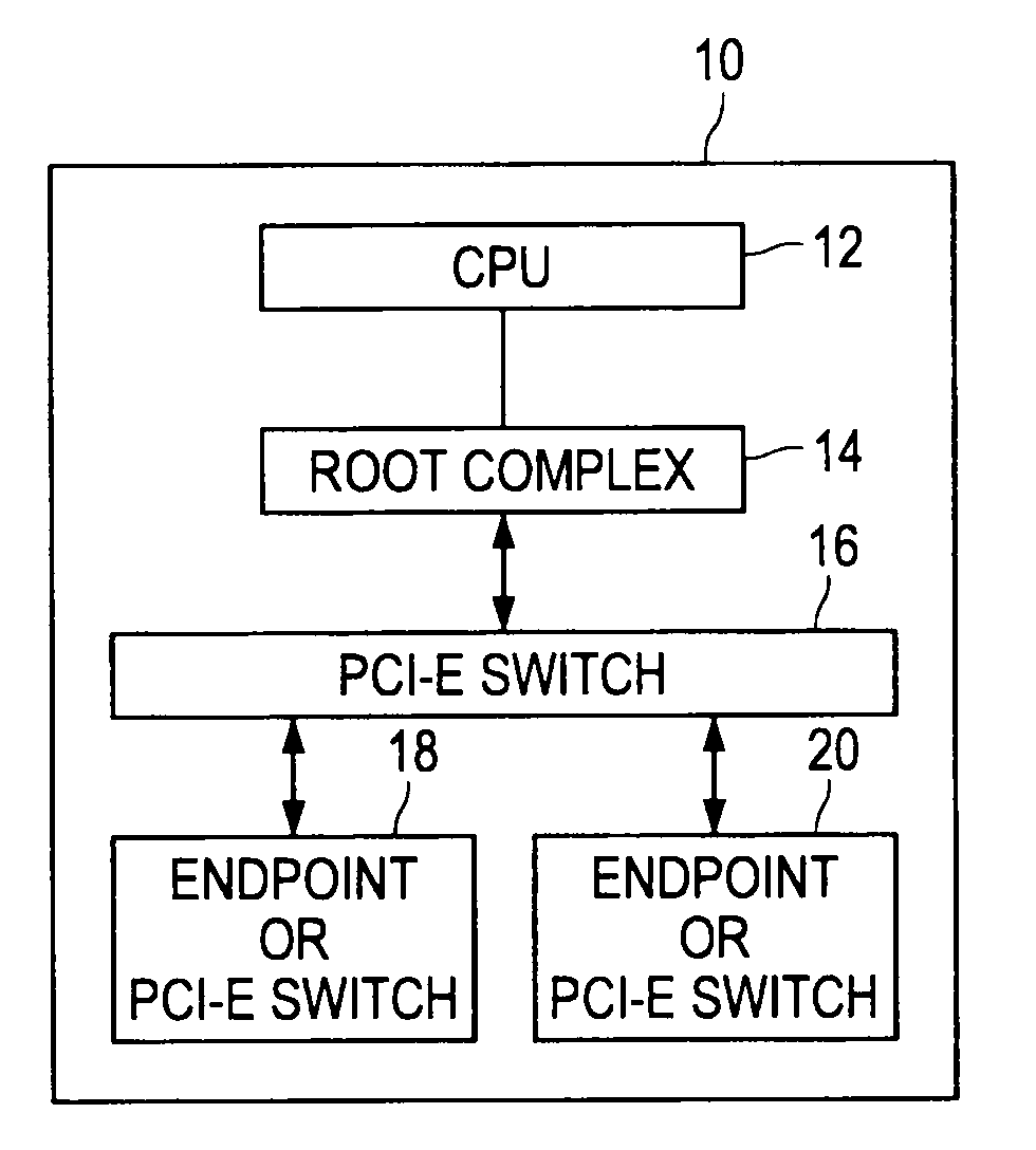
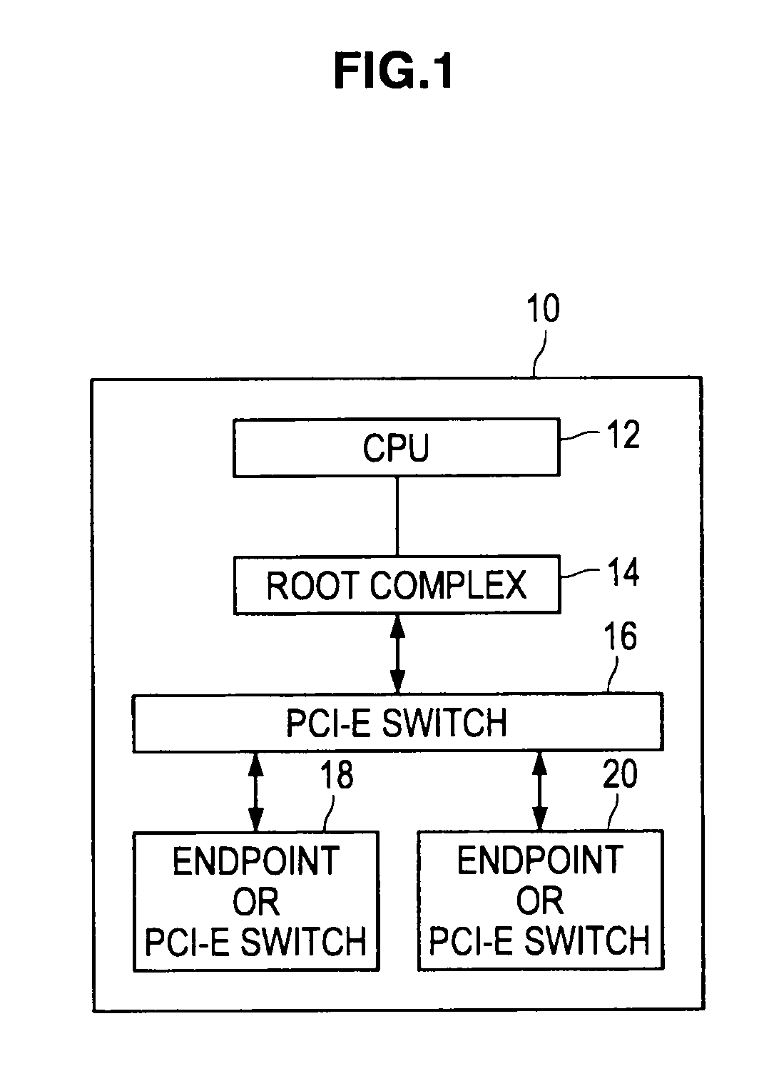
First, a device mounted with a PCI Express as a serial transfer interface will be explained. FIG. 1 is an explanatory diagram illustrating a schematic configuration of the device mounted with a PCI Express.

In FIG. 1, a device mounted with a PCI Express (PCIe) 10 includes a CPU 12, a root complex 14, a PCIe switch 16, and endpoints or PCIe switches 18, 20.

The root complex 14 is a device constituting the basis of a hierarchy, and may have one or more PCIe ports. The PCIe switch 16 is a device for adding the PCIe ports.

In the configuration of PCIe, the termination of a bus is always a downstream port, and in conformity with the PCIe standard of the PCI-SIG, only endpoints or PCIe switches 18, 20 may be connected to the downstream port.

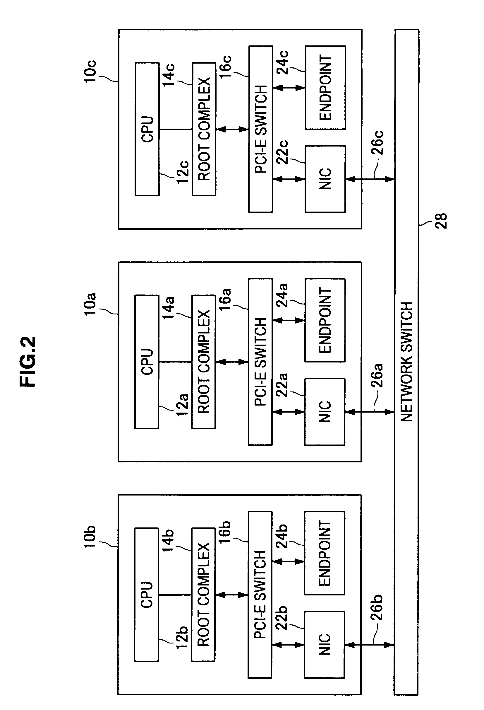
Next, Data transfer between devices each mounted with a PCI Express by use of network will be explained. FIG. 2 is an explanatory diagram illustrating data transfe...


PUM


Abstract

There is provided a data transfer apparatus including a first virtual network device which is connected to a downstream port of a first device mounted with a serial transfer interface, a first cable for extending a downstream port of a second device mounted with a serial transfer interface, a second virtual network device which is connected to the first cable, a second cable for extending a downstream port of a third device mounted with a serial transfer interface, a third virtual network device which is connected to the second cable, and a virtual network switch which is connected to the first virtual network device, the second virtual network device and the third virtual network device.

Description

BACKGROUND OF THE INVENTION1. Field of the InventionThe present invention relates to a data transfer apparatus.2. Description of the Related ArtIn the related art, networks as represented by Ethernet (registered trademark), Fibre Channel, InfiniBand and the like are used for data transfer between multiple devices.In order to configure a network, a network card such as Network Interface Card (NIC), Host Card Adapter (HCA) or the like, a network switch, and a network cable are used.When wideband at a data rate equal to or higher than 20 Gbps is to be realized in a network, in the case of Ethernet, multiple 10 Gigabit Ethernets (10 GbEther) need to be used, which leads to a very high-cost system. Also, in the case of InfiniBand, a very high-cost system will be created because it is necessary to support 4×DDR (Double Data Rate).Furthermore, when a wideband network needs to be used, bus speed in a device also needs to be high. As a wideband bus well known is a PCI Express (hereafter, ref...

Claims


Application Information

Patent Timeline
IPC IPC(8): G06F15/173H04L12/28
CPCH04L49/70H04L49/109H04L49/30
Inventor INOMATA, NAOKI
Owner SONY CORP
Why Eureka
Eureka Blog
Learn More