MEMS pressure sensor

a pressure sensor and sensor technology, applied in the field of mems pressure sensors, can solve the problems of pressure dependence of the performance of resonant mems devices, easy spoiled vacuum, and sensitivity to gas pressur

Active Publication Date: 2011-05-12
SCIOSENSE BV
View PDF9 Cites 29 Cited by
  • Summary
  • Abstract
  • Description
  • Claims
  • Application Information

AI Technical Summary

Benefits of technology

[0036]In one example, separate resonator elements can be used; one for the MEMS device (e.g. resonator or oscillator) and one for the pressure sensor. However, the resonant MEMS element (of the MEMS device) can comprise a MEMS resonator element controlled to vibrate in a lateral mode (bulk mode shape), and wherein the same MEMS resonator element is controlled to vibrate in a vertical resonant mode (out-of-plane mode shape) to form the resonant element of the MEMS pressure sensor. In this way, a single resonator element can perform the MEMS device function as well as the pressure sensor function. The resonator element when controlled to vibrate in a lateral mode then can comprises a bulk mode resonator functioning as a timing device or frequency reference.

Problems solved by technology

Micro cavities have a very small volume (typically 200×200×2 μm3) and the vacuum will be easily spoiled by a leak or out-gassing.
For high-aspect ratio miniaturization like in MEMS devices, however, extremely high magnetic fields will be necessary to reach sufficiently long electron paths and thus sensitivity to the pressure of the gas;
The pressure dependence of the performance of resonant MEMS devices, like resonators and gyroscopes, is the result of damping effects.
However, the motional resistance of mechanical resonators is not very stable over time, which makes these sensors unreliable in measuring absolute pressure over time, particularly low pressures.

Method used


Image

  • MEMS pressure sensor
  • MEMS pressure sensor
  • MEMS pressure sensor

Examples


Embodiment Construction

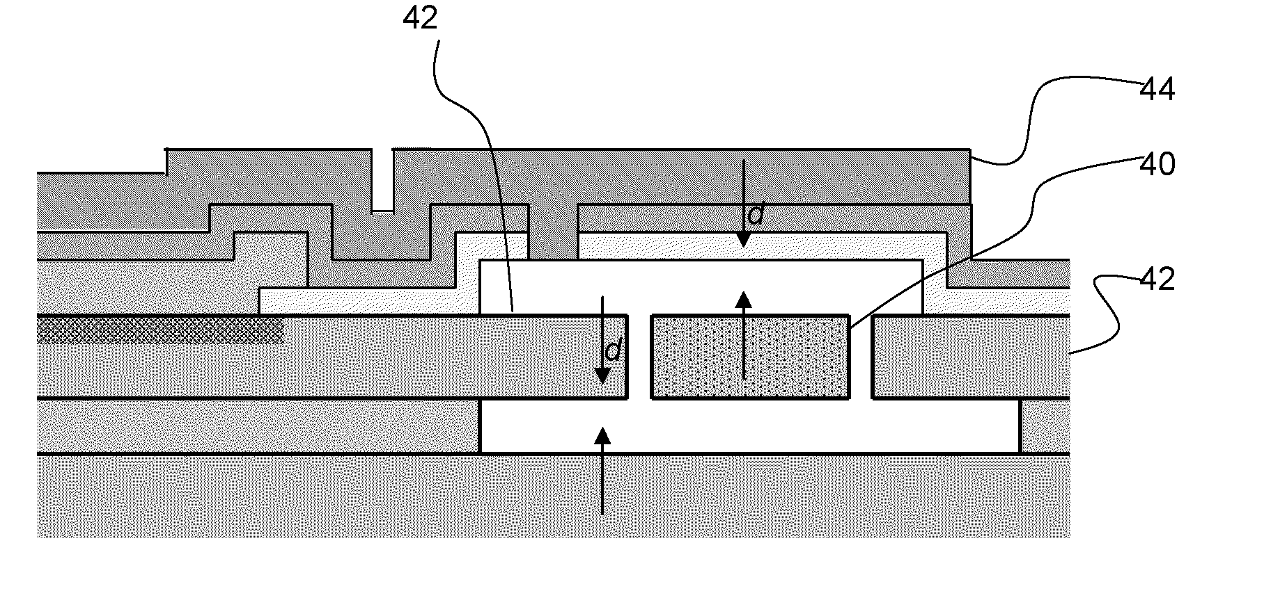
[0052]As mentioned above, it has been recognised that monitoring amplitudes or dissipation in a resonator signal can be used to indicate pressure. This invention is based on a different monitoring mechanism which affects the resonance frequency. If the gas film within the resonator structure can not escape fast enough, it will contribute to the spring constant k.

[0053]It can be assumed that the mean free path of the gas molecules is larger than the device dimensions, (i.e. >100 μm), for pressures in the range of 0.1 kPa, namely within the regime of a Knudsen gas, where viscosity is not considered.

[0054]In the equation of motion, Equation (1), the damping coefficient b and spring constant k can be decomposed to a contribution from the (silicon) structure bmat and a contribution due to gas damping bgas.

b=bmat+bgas  (6)

k=kmat+kgas  (7)

[0055]The damping coefficient bgas and elastic coefficient kgas are given by:

bgas=(pAτd)11+(ωτ)2(8)kgas=(pAd)(ωτ)21+(ωτ)2(9)

[0056]in which:

[0057]p is the...


PUM

PropertyMeasurementUnit
pressureaaaaaaaaaa
areaaaaaaaaaaa
thicknessaaaaaaaaaa

Abstract

A MEMS pressure sensor for sensing the pressure in a sealed cavity of a MEMS device, comprises a resonant MEMS device having a pressure sensor resonator element which comprises an array of openings. The resonant frequency of the resonant MEMS device is a function of the pressure in the cavity, with resonant frequency increasing with pressure. Over the pressure range 0 to 0.1 kPa, the average change in frequency is at least 10−6/Pa.
The invention is based on the recognition that for fast oscillation, the elastic force causes the resonance frequency to shift. Therefore, it is possible to sense the pressure by a device with resonance frequency that is sensitive to the pressure.

Description

[0001]This application claims the priority of European patent application no. 09172478.1, filed on Oct. 7, 2009, the contents of which are incorporated by reference herein.BACKGROUND OF THE INVENTION[0002]In the process of MEMS manufacturing, microstructures are usually encapsulated in a sealed micro cavity to maintain vacuum conditions for a proper operation of the MEMS device. Micro cavities have a very small volume (typically 200×200×2 μm3) and the vacuum will be easily spoiled by a leak or out-gassing. It is therefore important to have a means to monitor the pressure in the micro cavity either during product release, during qualification of the production process, or even during operation of the resonant MEMS device.[0003]FIG. 1 shows the pressure dependency of the oscillation amplitude (S12) for a bulk mode timing resonator with a frequency of 25.8 MHz. For pressures above 10 mbar (1 kPa) resonance amplitude starts to deteriorate.[0004]High frequency (HF) resonators (up to 100 ...

Claims


Application Information

Patent Timeline
Patent Type & Authority Applications(United States)
IPC IPC(8): G01L11/00
CPCG01L21/22G01L9/0019
Inventor SUIJLEN, MATTHIJSKONING, JAN JACOBBEIJERINCK, HERMAN COENRAAD WILLEM
Owner SCIOSENSE BV
Why Eureka
Try Eureka