High efficiency magnetic core electrical machine

a high-efficiency, magnetic core technology, applied in the direction of dynamo-electric converter control, motor/generator/converter stopper, etc., can solve the problems of increasing the need for high-efficiency electrical machines, increasing the cost of electro-magnetic induction motors and generators, and increasing the cost of current magnetic core electrical machine designs. unsuitable for many applications, to achieve the effect of reducing torque and/or voltage output, avoiding excessive output, and reducing the amount of magnetic flux

Inactive Publication Date: 2011-05-12
SULLIVAN JOHN T
View PDF6 Cites 35 Cited by
  • Summary
  • Abstract
  • Description
  • Claims
  • Application Information

AI Technical Summary

Benefits of technology

[0019]According to another aspect of the invention, mechanisms are provided to reduce the torque and/or voltage output of the electrical machine when operated as a generator at high speeds so as to avoid excessive output that might damage the load. The mechanisms may includes a plate or plates that reduce the amount of magnetic flux between the rotor magnets and stator poles, an actuator for increasing a distance between the rotor magnets and stator poles, and/or a voltage reduction circuit for reducing a voltage output of the electrical machine by switching fr...

Problems solved by technology

The need for high efficiency electrical machines has become increasingly critical as fossil fuel supplies become depleted and/or more expensive to extract.
However, motors and generators that utilize electro-magnetic induction continue to be less cost effective in many applications than fossil fuel based motors and generators, particularly for transportation and alternative power generation.
However, current magnetic core electrical machine designs are unsuitable for many applications because of performance problems resulting from the so-called “cogging” force that opposes movement of the rotor in both generators and motors.
On the other hand, at high...

Method used


Image

  • High efficiency magnetic core electrical machine
  • High efficiency magnetic core electrical machine
  • High efficiency magnetic core electrical machine

Examples


Embodiment Construction

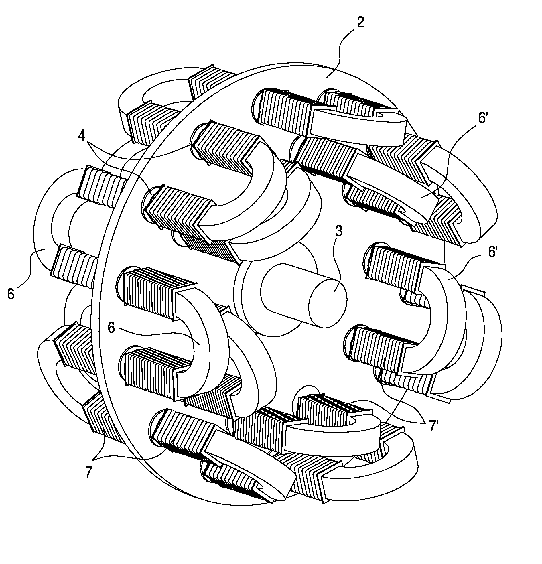
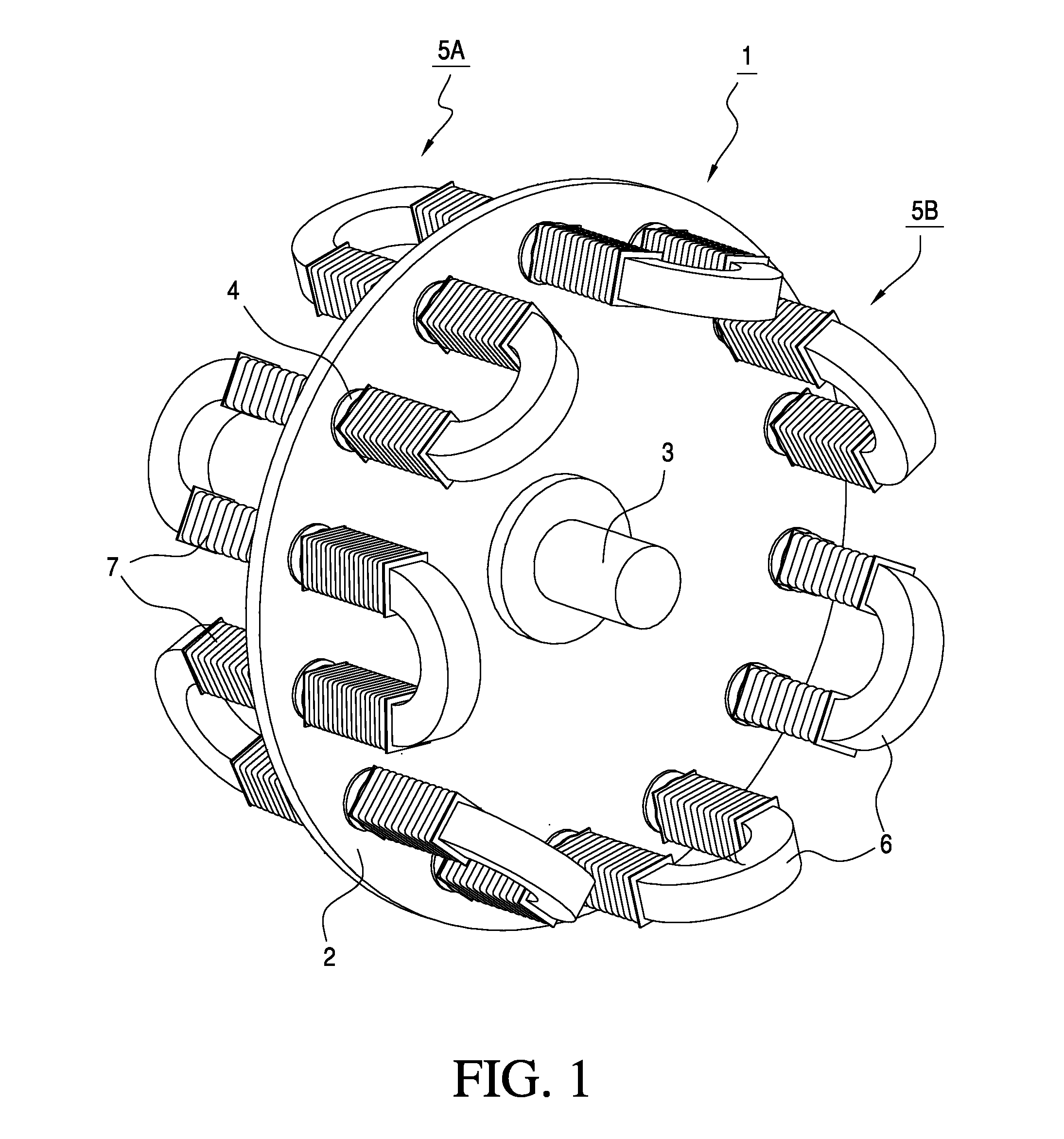
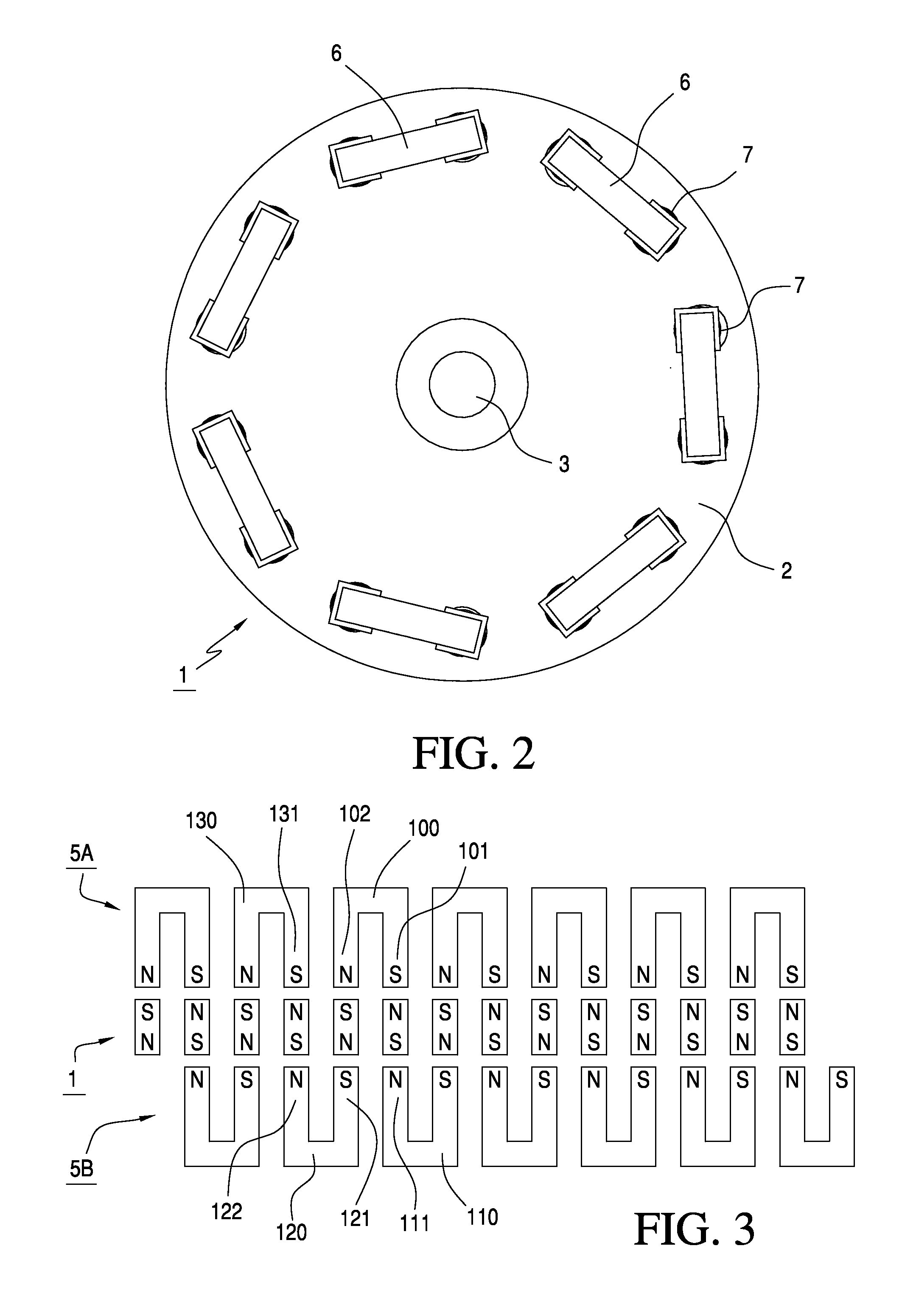
[0040]As illustrated in FIGS. 1-3, an electrical machine constructed in accordance with the principles of a preferred embodiment of the invention includes a rotor 1 made up of a non-magnetic plate 2 connected to a shaft 3 and having a plurality of permanent magnets 4 embedded or mounted therein, and a stator 5a,5b including coils 7 and a plurality of generally “U”-shaped high permeability cores or yokes 6 made, for example, of stacked silicon laminations or the like. The permanent magnets 4 and yokes 6 are arranged in series such that each yoke faces like poles of two different yokes on an opposite side of the rotor, thereby providing a continuous magnetic circuit that extends 360° around the circumference of the stator, as best seen in FIG. 3. In particular, as illustrated in FIG. 3, the yokes are staggered such that a first pole 101 of a first yoke 100 on a first side of said rotor faces a first pole 111 of a second yoke 110 on a second side of said rotor, a second pole 102 of sai...


PUM


Abstract

A magnetic core electrical machine includes a plurality of “U”-shaped stator yokes arranged circumferentially with respect to a rotor and either staggered to form a continuous flux return path or displaced relative to permanent magnets of the rotor in order to reduce cogging. Various mechanisms and/or circuits are provided to limit an output of the electrical machine at high speeds, and boost the voltage output at low speeds.

Description

BACKGROUND OF THE INVENTION[0001]1. Field of the Invention[0002]This invention relates to electrical machines of the type having a magnetic core. The electrical machines of the invention may be used as motors or generators, and may include any of the following features:[0003]a plurality of “U”-shaped stator yokes arranged circumferentially with respect to the rotor and staggered on opposite sides of the rotor to form a continuous flux return path;[0004]a plurality of “U”-shaped stator yokes oriented radially with respect to the rotor, the poles of the stator yokes being shifted relative to the rotor magnets to provide an asymmetric pole arrangement that minimizes “cogging” due to attraction between the magnetic stator core and permanent magnets in the rotor of the electrical machine, the rotor magnets and yokes optionally having an odd / even numerical relationship;[0005]a plurality of “C” shaped stator yokes arranged around a periphery of the rotor, in which the rotor magnets and yok...

Claims


Application Information

Patent Timeline
IPC IPC(8): H02K21/24H02K23/44H02P6/08H02K9/22H02K16/00
CPCH02K16/00H02K21/026Y02E10/725H02K21/24H02K29/03H02K21/028H02K16/04Y02E10/72
Inventor SULLIVAN, JOHN T.PARKS, STEVE
Owner SULLIVAN JOHN T
Why Eureka
Try Eureka