Liquid ejection device and liquid ejection printer

a technology of liquid ejection and printer, which is applied in the direction of printing, fluid jet surgical cutters, other printing apparatus, etc., can solve the problems of large power loss caused by damping resistor, and achieve the effect of reducing power loss

Active Publication Date: 2011-05-12
COLUMBIA PEAK VENTURES LLC
View PDF7 Cites 32 Cited by
  • Summary
  • Abstract
  • Description
  • Claims
  • Application Information

AI Technical Summary

Benefits of technology

[0006]An advantage of some aspects of the invention is to provide a liquid ejection device and a liquid ejection printer that can reduce a power loss due to a damping resistor.

Problems solved by technology

However, when the actuator is a capacitive load such as a piezoelectric element, the Lowpass Filter needs a damping resistor because of the absence of a resistance component, resulting in a large power loss due to this damping resistor.

Method used


Image

  • Liquid ejection device and liquid ejection printer
  • Liquid ejection device and liquid ejection printer
  • Liquid ejection device and liquid ejection printer

Examples


first embodiment

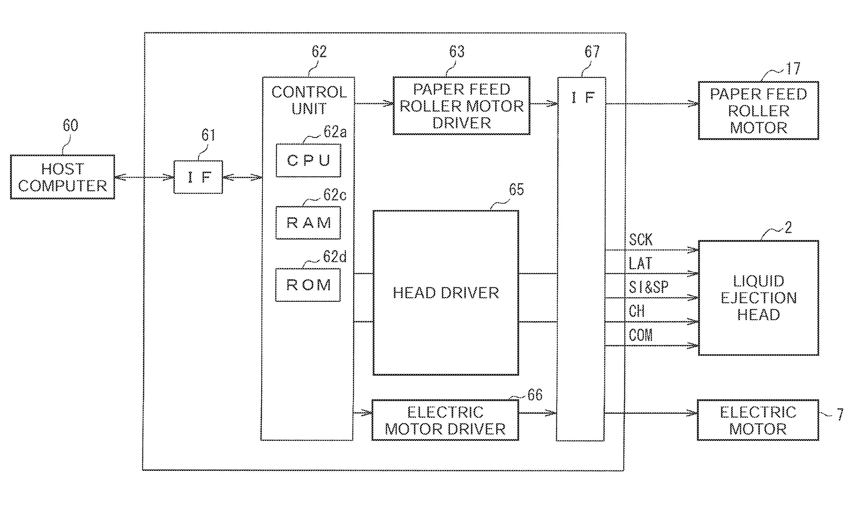
[0029]As a liquid ejection device of the invention, a liquid ejection device used in a liquid ejection printer will be described.

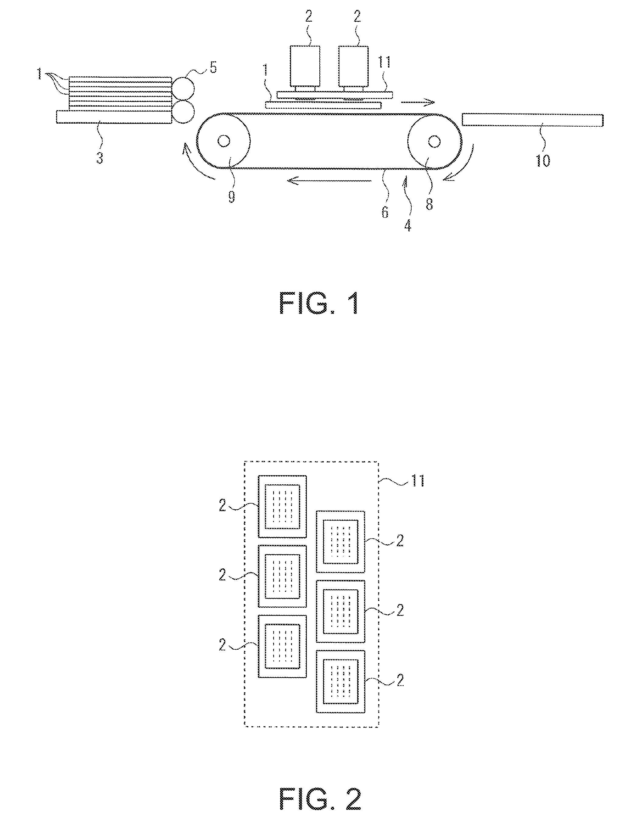
[0030]FIG. 1 is a schematic configuration diagram of a liquid ejection printer of the first embodiment. This liquid ejection printer is a line head printer in which a printing medium 1 is conveyed from left to right in an arrow direction in FIG. 1 and printing is performed thereon in a printing region located along a path on which the printing medium 1 is being conveyed.

[0031]In FIG. 1, a plurality of liquid ejection heads 2 are provided above a conveying line of the printing medium 1. The liquid ejection heads 2 are disposed so that they form two lines in a printing medium conveying direction and are arranged next to one another in a direction intersecting the printing medium conveying direction, and are fixed to a head fixing plate 11. On the lowermost face of each liquid ejection head 2, a large number of nozzles are formed, and this face is called a no...

second embodiment

[0055]In the actuator drive circuit in the second embodiment, a closed loop formed of the adder-subtractor 31, the modulator 26, the digital power amplifier 28, the Lowpass Filter 29, the capacitance of the actuator 22, and the compensator 32 is shown in FIG. 15. The transfer characteristic of the inverse filter 23 is assumed to be C. The transfer characteristic GO of the whole system including the inverse filter 23 is expressed in the following formula (2).

C(f0)·G(f0,N)=C(f0)A·H(f0,N)1+A·H(f0,N)·β(f0)=G0(2)

[0056]As described in WO 2007 / 083669, for example, when the number of actuators 22 which are driven changes, the frequency characteristic of the closed loop changes. The feature is shown in FIG. 16. In this case, as mentioned above, since the resonance of the closed loop is suppressed by the negative feedback signal CPST from the compensator 32, the frequency characteristic changes as the attenuation start frequency changes, and the larger the number of actuators 22 which are dri...


PUM


Abstract

A liquid ejection device includes: a drive waveform generator generating a drive waveform signal; a modulator performing pulse modulation on a signal from the drive waveform generator to provide a modulated signal; a digital power amplifier performing power amplification on the modulated signal to provide an amplified digital signal; a Lowpass Filter smoothing the amplified digital signal to provide a drive signal of an actuator; a compensator advancing the phase of the drive signal to provide a negative feedback signal; and a subtractor providing a differential signal between the drive waveform signal and the negative feedback signal as an input signal to the modulator.

Description

BACKGROUND[0001]1. Technical Field[0002]The present invention relates to a liquid ejection device which performs power amplification on a drive signal to an actuator ejecting a liquid, and is suitable for a liquid ejection printer which prints characters, images, etc. by ejecting a minute liquid droplet out of a nozzle of a liquid ejection head and forming fine particles (dots) on a printing medium.[0003]2. Related Art[0004]In a liquid ejection printer, an actuator such as a piezoelectric element is provided and a predetermined drive signal has to be applied to this actuator to eject a liquid out of a nozzle of a liquid ejection head. Since this drive signal has a relatively high voltage, it is necessary to perform power amplification on a drive waveform signal serving as a reference of the drive signal by using a power amplifier. Therefore, in JP-A-11-204850, a digital power amplifier which has an extremely small power loss compared to an analog power amplifier and can be made comp...

Claims


Application Information

Patent Timeline
Patent Type & Authority Applications(United States)
IPC IPC(8): B41J29/38
CPCB41J2/04541B41J2/04548B41J2/0455B41J2/04573B41J2/0457B41J2/04593B41J29/38A61B17/3203B41J2/04581
Inventor OSHIMA, ATSUSHITABATA, KUNIOMIYAZAKI, SHINICHIYOSHINO, HIROYUKIIDE, NORITAKA
Owner COLUMBIA PEAK VENTURES LLC
Why Eureka
Try Eureka