Gas turbine having an improved cooling architecture

Active Publication Date: 2011-05-12
GENERAL ELECTRIC TECH GMBH
View PDF18 Cites 15 Cited by
  • Summary
  • Abstract
  • Description
  • Claims
  • Application Information

AI Technical Summary

Benefits of technology

[0007]An aspect of the invention is to provide a thermal machine, in particular a gas turbine, such that the load on the the

Problems solved by technology

The non-uniformities on the hot-gas side re

Method used


Image

  • Gas turbine having an improved cooling architecture
  • Gas turbine having an improved cooling architecture
  • Gas turbine having an improved cooling architecture

Examples


Embodiment Construction

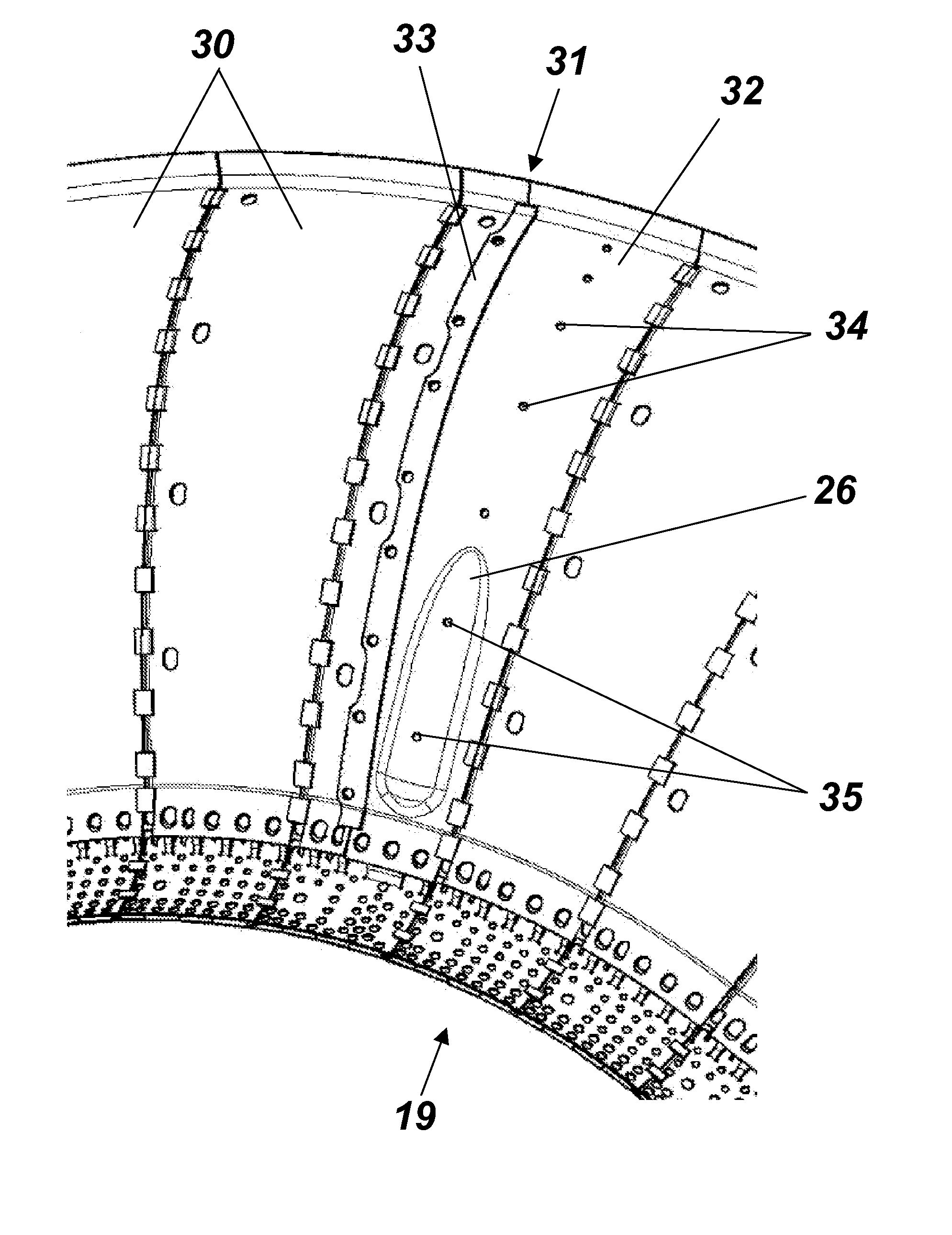
[0022]For the purposes of the invention, the distribution of the cooling air is influenced by a (local) adaptation of the cooling channel cross-sectional profile in conjunction with fittings which are present in the cooling channel such that a local adaptation of the cooling air mass flow and a local adaptation of the heat transfer between the shell and the cooling air are created. The cooling channel cross section is in this case defined by the existing contour of the inner and outer shells and modified contouring, that is to say contouring whose shape has been adapted, of the cooling air plates (cooling shirts) which are mounted on the inner and outer shells.

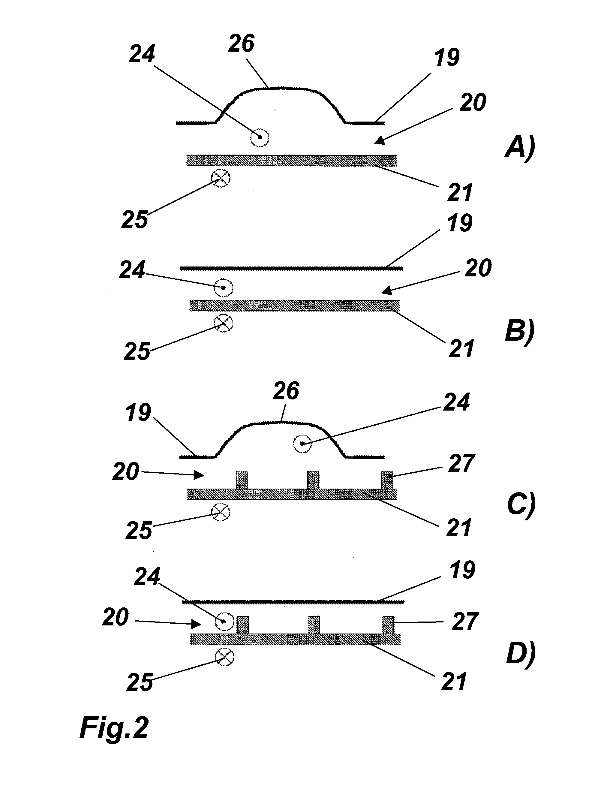
[0023]FIG. 2B shows, in a section transversely with respect to the flow direction of the cooling air 24 and of the hot gas 25 which is flowing in the opposite direction, a cooling channel which is formed between the shell 21 and the cooling shirt 19 and has a flow cross section which is constant for the illustrated detail. Acc...


PUM


Abstract

A thermal machine includes a hot gas channel; a shell bounding the hot gas channel; a cooling shirt surrounding the shell; and a cooling channel disposed between the shell and the cooling shirt and configured to convection cool the hot gas channel with a cooling medium, wherein the cooling shirt includes at least one local divergence in the guidance of the cooling medium so as to compensate for non-uniformities in at least one of a thermal load on the shell and a flow of the cooling medium in the cooling channel.

Description

CROSS REFERENCE TO PRIOR APPLICATIONS[0001]This application is a continuation of International Application No. PCT / EP2009 / 051763, filed Feb. 16, 2009, which claims priority to Swiss Patent Application No. CH 00244 / 08, filed Feb. 20, 2008. The entire disclosure of both applications is incorporated by reference herein.FIELD[0002]The present invention relates to the field of thermal machines, and relates in particular to a thermal machine.BACKGROUND[0003]Gas turbines, for example inter alia under the type designation GT13E2, are operated with an annular combustion chamber. The combustion itself takes place preferably, but not exclusively, via premixing burners (referred to in the following text for short as burners), such as those disclosed in EP-A1-321 809 or EP-A1-704 657, with these documents and the further development of these premixing burners derived therefrom being an integrating component of this application. By way of example, an annular combustion chamber such as this is dis...

Claims


Application Information

Patent Timeline
IPC IPC(8): F02C7/16
CPCF01D9/023F01D25/12F23R2900/03045F05D2260/2214F05D2260/221F05D2260/2212F05D2260/22141F05D2260/201
Inventor HAEHNLE, HARTMUTJONES, RUSSELL BONDVOGEL, GREGORYTSCHUOR, REMIGI
Owner GENERAL ELECTRIC TECH GMBH
Why Eureka
Try Eureka