Improved radiant burner

a radiant burner and burner plate technology, applied in the direction of burners, burner materials, combustion types, etc., can solve the problems of early failure local overheating of the burner plate, and increased radiation output of the radiant burner plate, so as to achieve less emissivity, energy efficiency, and higher radiative output

Inactive Publication Date: 2011-05-12
SOLARONICS +1
View PDF35 Cites 20 Cited by
  • Summary
  • Abstract
  • Description
  • Claims
  • Application Information

AI Technical Summary

Benefits of technology

[0007]The radiant burner plate has multiple levels of burner surfaces. In a preferred embodiment, these multiple levels are arranged in rows and are alternating per one row of through holes / perforations on the radiant burner plate. An example of such burner plate can be found in FIG. 1, or alternatives in FIGS. 2 and 3. These types of burner plates, as such, provide less emissivity compared to ceramic tiles with honeycomb or similar perforation patterns. This is due to the multiple level burner surface, wherein the lower levels of the burner surface of the radiant burner plates provide a higher radiative output because the sides of the rows also heat up and provide an additional radiative output, but the highest level of burner surface does not have such additional radiative output. So the overall radiative output, and therefore also the energy efficiency, of such multilevel radiant burner plate as such, is lower than honeycomb-like perforations in the radiant burner plate.
[0008]However, although radiant burner plates are used which as such have a lower radiative output, it was surprisingly observed that by the use of such a second radiant screen near the radiant burner plates, the radiative output of the radiant burner plates can be increased without leading to local overheating of the burner plates, as this would result in early failure of the radiant burner plates. This might be explained, without pretending to be scientifically correct, by the fact that the back radiation of the second radiant screen on the radiant multilevel burner plates is the highest on the highest level of the burner surface as this is closest to the second radiant screen. This highest level thereby also heats up more than the lower levels of the burner surface, which are at a bigger distance from this second radiant screen. As these lower levels in the burner surface of the radiant burner plates were already at higher temperatures by the effect of the flames heating up the surface surrounding the cavity wherein the perforations open, the overall effect of the present invention is that the different levels in the burner surface of the radiant burner plates are at the same temperature when in use. Stated otherwise, a greater temperature uniformity of the burner surface of the radiant burner plate is attained. The person skilled in the art will understand that this greater temperature uniformity combined with the plurality of radiant screens results in a significant higher energy efficiency of the complete radiant burner. In a preferred embodiment, the distance between the second radiant screen and the highest level of burner surface of the at least one radiant burner plates is between 3 and 50 mm. More preferably, the distance between the second radiant screen and highest level of the radiant burner plate is between 5 and 30 mm, even more preferably between 10 and 25 mm, most preferably between 15 and 20 mm. In a preferred embodiment, the second radiant screen is positioned such that the second radiant screen follows the direction of the rows of the highest level of burner surface of the radiant burner plate.

Problems solved by technology

However, although radiant burner plates are used which as such have a lower radiative output, it was surprisingly observed that by the use of such a second radiant screen near the radiant burner plates, the radiative output of the radiant burner plates can be increased without leading to local overheating of the burner plates, as this would result in early failure of the radiant burner plates.

Method used


Image

  • Improved radiant burner
  • Improved radiant burner
  • Improved radiant burner

Examples


Embodiment Construction

[0018]Example embodiments of the present invention will now be described with reference to FIGS. 1 to 7.

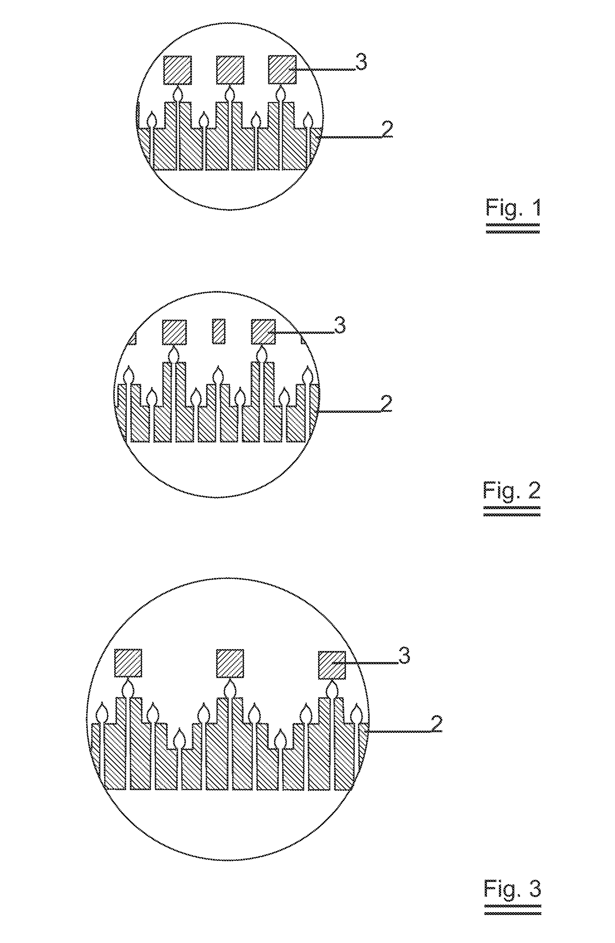
[0019]FIGS. 1 to 3 show cross sections of example embodiments of radiant burner plates which might be used in the present invention. FIG. 1 shows two levels of burner surface of the radiant burner plate 2, FIGS. 2 and 3 show three levels of burner surface, in two alternative forms.

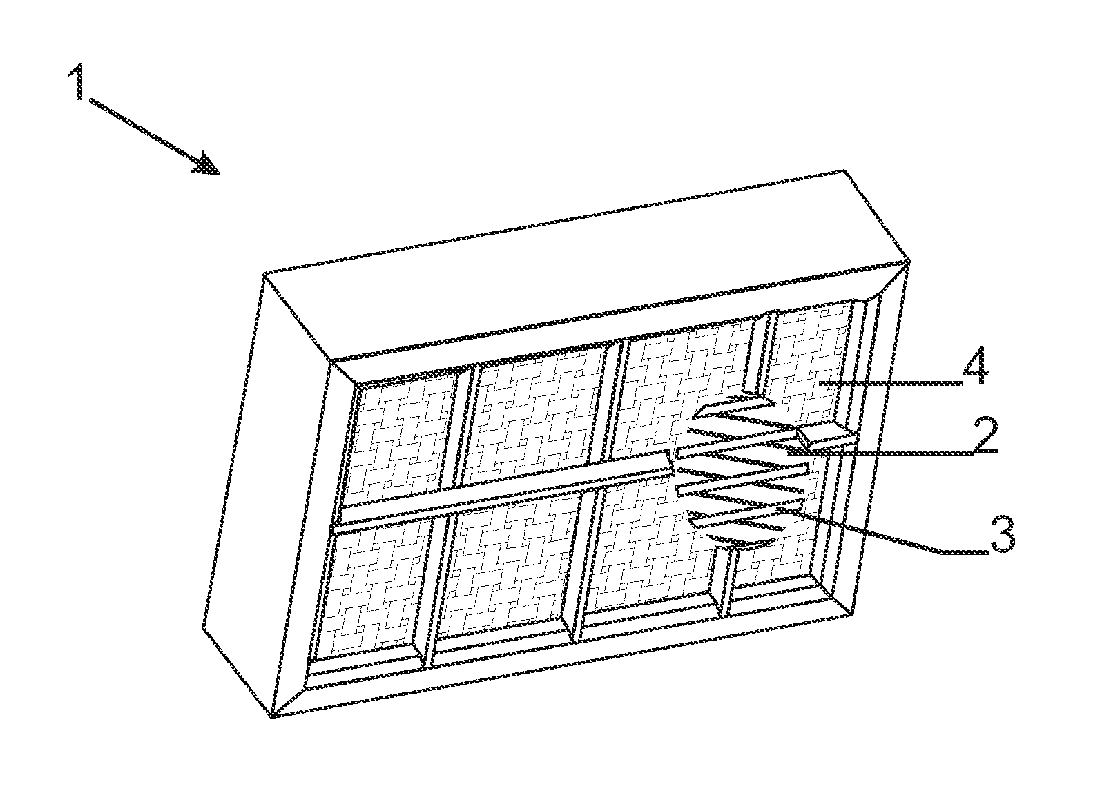
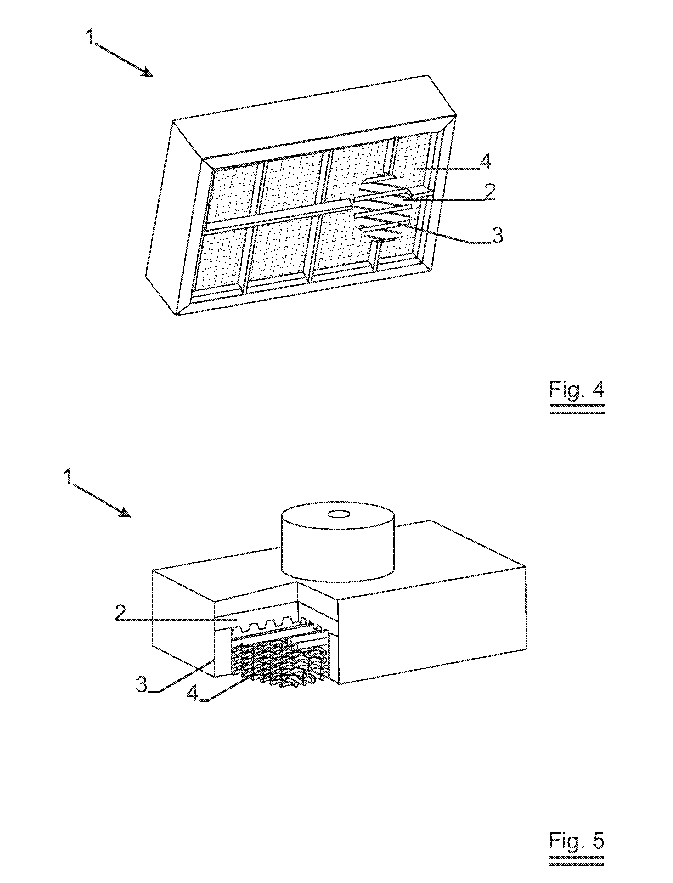
[0020]FIGS. 4 and 5 show an example embodiment of the present invention. The first radiant screen 4 is a highly heat resisting metal grid fabricated from highly heat resistant steel grades, such as high level stainless steel grades like Kanthal APM or APMT, different grades of FeCrAl alloy designed for high temperature corrosion, Chrome / Nickel steel grades like Avesta 253 MA, 153 MA, Inconel 601, Incoloy 800HT, Incoloy MA956. The second radiant screen 3 is made of a highly heat resisting ceramic material, in this example aluminium or zirconium oxide, aluminium titanate, silicon oxide, corundum or mullite...


PUM


Abstract

A radiant burner comprises a body defining a premixing chamber and a combustion chamber. The premixing chamber is separated from the combustion chamber by at least one radiant burner plate (2) which has multiple levels of burner surface. The combustion chamber is further limited by a first radiant screen (4). The radiant burner further comprises a second radiant screen (3) in the combustion chamber. The second radiant screen is spaced from, but near and parallel to the radiant burner plate(s), such that this second radiant screen acts as an extended burner surface and also heats up said at least one radiant burner plate when in use.

Description

TECHNICAL FIELD[0001]The present invention relates to radiant burners comprising a radiant burner plate and a screen.BACKGROUND ART[0002]Radiant burners comprising a radiant burner plate and a screen are known e.g. from U.S. Pat. No. 4,799,879 or EP0539279. The screen together with the radiant burner plate provides the radiative output of the burner, which averages at levels around 50% efficiency. In the past the radiative output of the burners has been increased by modification of the radiant burner plate from a radiant burner plate with rows of through holes or perforations serving to channel the mixture of air and combustion agent from the rear of the plate to the radiating face, to a radiant burner plate wherein the through holes or perforations are arranged in what is nowadays called honeycomb pattern as described in e.g. U.S. Pat. No. 4,569,657 or U.S. Pat. No. 4,799,879. This or similar modifications of the radiant burner plate increased the temperature level and consequently...

Claims


Application Information

Patent Timeline
Patent Type & Authority Applications(United States)
IPC IPC(8): F23D14/14
CPCF23D14/14F23D2203/103F23D2212/20F23D2212/10F23D2203/106F23D14/148F23D14/145F23D14/149
Inventor CLAERBOUT, KOENDUMORTIER, GEERTOLALDE, VALERIE
Owner SOLARONICS
Why Eureka
Try Eureka