Photoacoustic measurement apparatus

a measurement apparatus and photoacoustic technology, applied in the field of measurement apparatus, can solve the problems of time delay, inability to increase the amount of light reaching the deep part of the tissue, and inability to detect the propagation time with the signal, etc., and achieve the effect of high accuracy

Inactive Publication Date: 2011-05-12
CANON KK
View PDF13 Cites 50 Cited by
  • Summary
  • Abstract
  • Description
  • Claims
  • Application Information

AI Technical Summary

Benefits of technology

[0025]It is possible to realize a measurement apparatus capable of measuring a position and a size of an absorber with high accuracy by detec...

Problems solved by technology

However, the conventional measurement apparatus for measuring spectral characteristics of the inside of a biological tissue has a following problem.
However, the position closest to the transducer and the position farthest from the transducer are in a direction different from the light incidence direction, and hence the propagation time cannot be detected with the signal of the largest intensity as described above.
2543-2557, a pressed inspection object is illuminated on the both sides thereof one side by one...

Method used


Image

  • Photoacoustic measurement apparatus
  • Photoacoustic measurement apparatus
  • Photoacoustic measurement apparatus

Examples


example 1

[0059]In Example 1, a structural example of a measurement apparatus to which the present invention is applied is described.

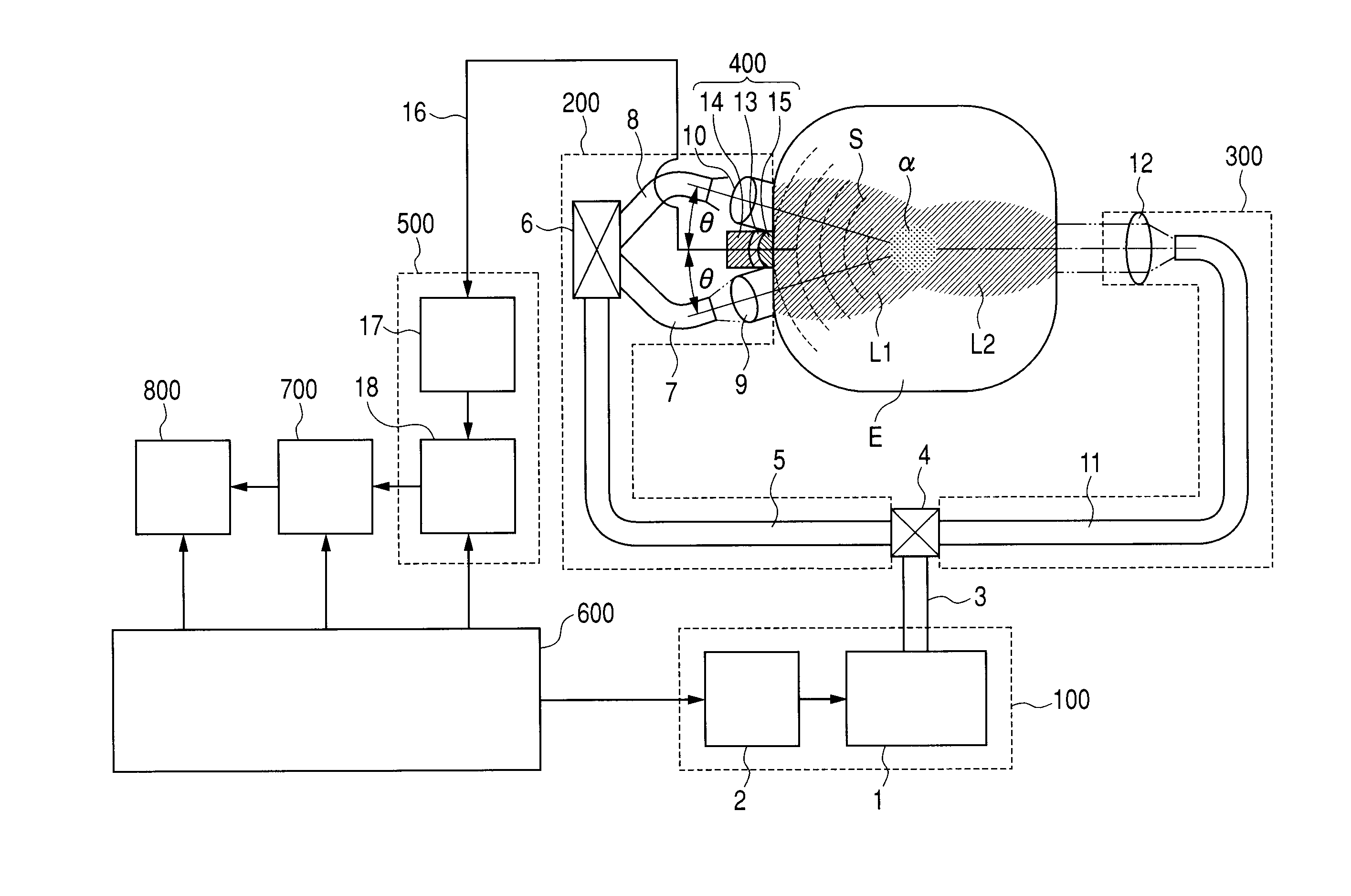
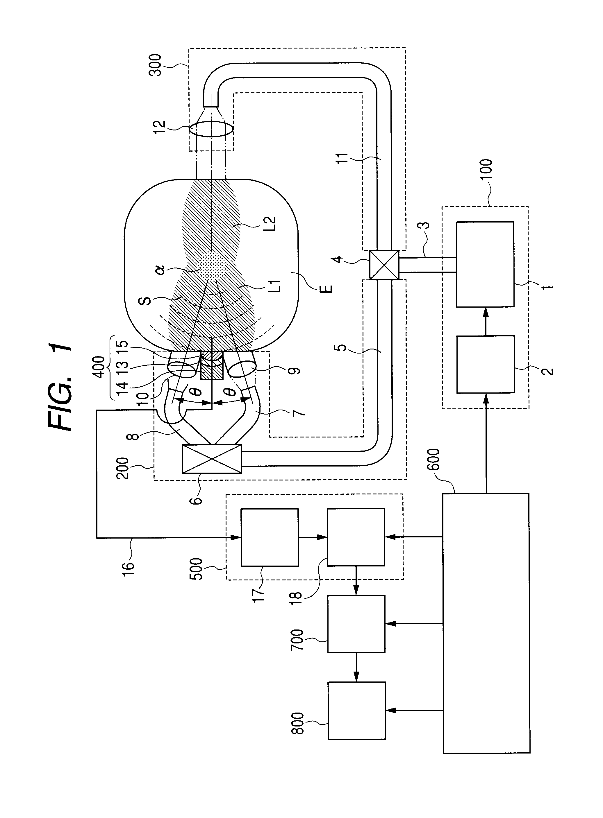
[0060]FIG. 1 is a diagram illustrating a schematic structure of the measurement apparatus according to this example.

[0061]The measurement apparatus of this example includes a pulse beam generator 100 (i.e., a light source unit), a first illumination optical system 200 (i.e., a first illumination optical unit), and a second illumination optical system 300 (i.e., a second illumination optical unit). In addition, the measurement apparatus includes an ultrasonic detector 400 (i.e., an acoustic signal detection unit), a signal analyzer 500, a controller 600, a memory 700, and a display 800.

[0062]An inspection object E is a biological tissue such as a breast, for example. An absorber α has an absorption larger than peripheral tissues and has a spherical shape, for example.

[0063]A schematic process for measuring the inspection object E by the measurement apparatus havi...

example 2

[0211]In Example 2, a structural example of a measurement apparatus having a form different from that of Example 1 is described. FIG. 14 is a diagram illustrating a schematic structure of the measurement apparatus according to this example.

[0212]A basic structure of the measurement apparatus of this example is similar to the structure described above in Example 1, and a structural member denoted by the same numeral has the same function as that described above in Example 1.

[0213]In this example, a first drive mechanism 901 and a second drive mechanism 902 are newly disposed. The first drive mechanism 901 changes positions of a first illumination optical system 205 and the ultrasonic detector 403 with respect to the inspection object E. The second drive mechanism 902 changes a position of a second illumination optical system 301 with respect to the inspection object E.

[0214]Those drive mechanisms are controlled so that the individual structural members are scan-driven with respect to...

example 3

[0265]FIG. 17 is a schematic block diagram of a measurement apparatus according to Example 3 to which the present invention can be applied.

[0266]The basic structure of the measurement apparatus is similar to the structure of Example 2 illustrated in FIG. 14, and structural members denoted by the reference symbols have the same function as those described above in Example 2.

[0267]In this example, a plate drive mechanism 904 is disposed additionally.

[0268]The plate drive mechanism 904 includes a slide guide 54 and a motor 55.

[0269]One end of the slide guide 54 is coupled to the second plate 26 contacting with the inspection object E, and the position of the second plate 26 can be moved in the arrow illustrated in FIG. 17. As an example of the member forming the slide guide 55, it is possible to use a ball screw, a linear guide, or the like.

[0270]Energy intensity of the light applied to the inspection object E is attenuated largely by influences of absorption and dispersion in the biol...


PUM


Abstract

A measurement apparatus capable of measuring a position and a size of an absorber with high accuracy, which includes: a light source unit for emitting a pulse beam; an illumination optical unit for leading the pulse beam emitted by the light source unit to an inside of an inspection object; and an acoustic signal detection unit for detecting a photoacoustic signal generated by the pulse beam in which the illumination optical unit includes a first and second illumination optical units that are arranged so that the inspection object is irradiated with the pulse beam from both sides thereof opposingly; and the acoustic signal detection unit is provided so that a detection surface of the acoustic signal detection unit is positioned on the same side as that of one of irradiation surfaces of the inspection object which the first and second illumination optical units irradiate with the pulse beam.

Description

TECHNICAL FIELD[0001]The present invention relates to a measurement apparatus for measuring spectral characteristics of the inside of a biological tissue. In particular, the present invention is applicable to a measuring apparatus that utilizes a photoacoustic effect.BACKGROUND ART[0002]The measurement apparatus for measuring spectral characteristics of the inside of a biological tissue is used for determining formation of new blood vessels or oxygen metabolism of hemoglobin attending on growth of tumor based on light absorption characteristics of a specific substance such as hemoglobin contained in blood, to thereby utilize the results for diagnosis.[0003]Such an apparatus uses a near infrared beam having a wavelength of approximately 600 to 1,500 nm with excellent transmittance property for a biological tissue.[0004]As a method of measuring spectral characteristics of the inside of a biological tissue, there is known a method utilizing a photoacoustic effect. An apparatus using th...

Claims


Application Information

Patent Timeline
IPC IPC(8): A61B5/05
CPCA61B5/0059A61B5/0091A61B5/0095G01N2021/1706A61B5/4312G01N21/1702A61B5/14546
Inventor NISHIHARA, HIROSHIFUKUTANI, KAZUHIKONAKAJIMA, TAKAO
Owner CANON KK
Why Eureka
Try Eureka