Process and apparatus for separating hydrocarbons from produced water

a technology of hydrocarbons and equipment, applied in the direction of flotation, solid separation, water/sludge/sewage treatment, etc., can solve the problems of optimally small bubbles or optimal bubble distribution, and achieve the effect of minimizing the size of the oil-water interface, maximizing the effectiveness of the bubble in removing contaminants, and optimizing uniformity

Inactive Publication Date: 2011-05-19
1139076 ALBERTA
View PDF25 Cites 22 Cited by
  • Summary
  • Abstract
  • Description
  • Claims
  • Application Information

AI Technical Summary

Benefits of technology

[0010]In accordance with the method of the present invention, gas bubbles are generated inside the treatment vessel, and are thus introduced immediately and directly into the water being treated. The bubbles are created using an aerator disposed inside the treatment vessel and immersed in the water being treated. Moreover, the particular type of aerator used in preferred embodiments of the invention may be readily adapted to generate bubbles much smaller than the bubbles typically produced in known processes. In addition, the design of the aerator and its orientation in the treatment vessel are such that operation of the aerator to generate bubbles is also effective to mix the bubbles with optimal uniformity into the water in the vessel, thus maximizing the effectiveness of the bubbles in removing contaminants from water in all regions within the vessel. As well, the process vessels are geometrically configured to minimize the size of the oil-water interface (or contaminant-water interface) to facilitate removal of separated oil (or other contaminants) with minimal loss of water.

Problems solved by technology

This methodology is not ideally conducive to the creation of optimally small bubbles or optimal bubble distributions, in part because the bubbles are more susceptible to breakdown or agglomeration into larger bubbles during transport to the treatment vessel.

Method used


Image

  • Process and apparatus for separating hydrocarbons from produced water
  • Process and apparatus for separating hydrocarbons from produced water
  • Process and apparatus for separating hydrocarbons from produced water

Examples


Embodiment Construction

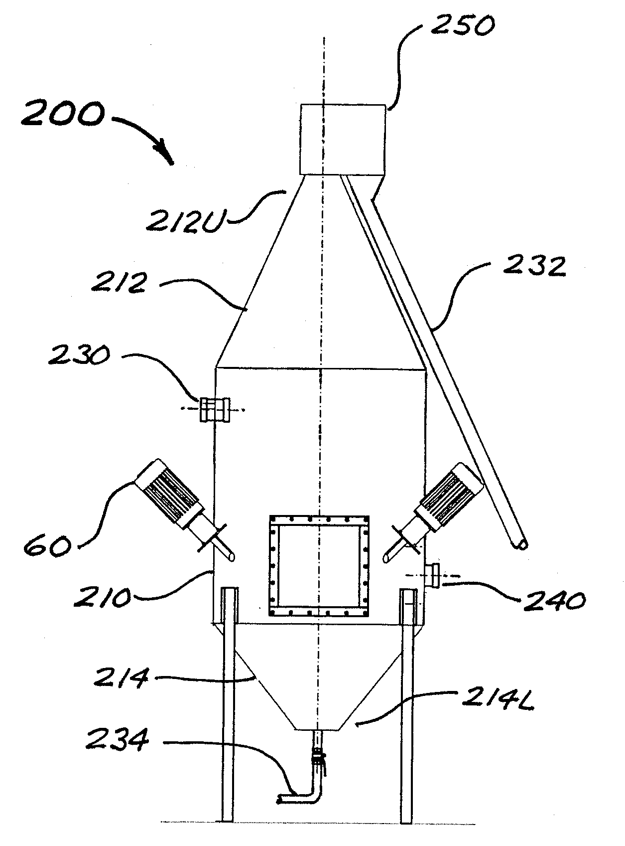
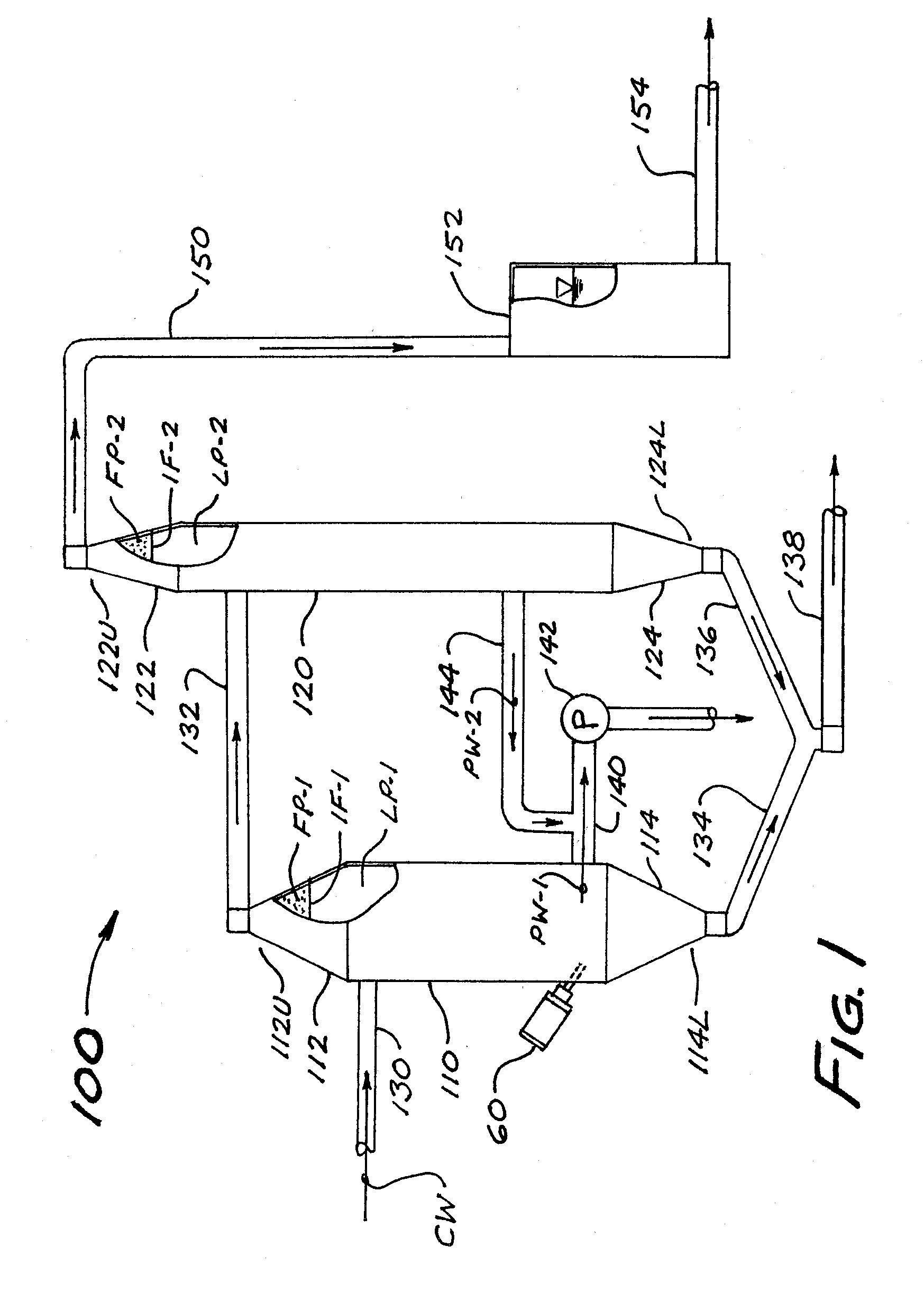
[0026]The process of the present invention may be understood with reference to FIG. 1, which is a schematic depiction of a first embodiment 100 of the apparatus of the invention. Apparatus 100 includes a generally cylindrical and vertically-oriented gas induction tank, referred to herein as primary separation tank 110. Primary tank 110 includes a preferably conical upper section 112 (having an upper end 112U) and a preferably conical lower section 114 (having a lower end 114L). Apparatus 100 further includes a generally cylindrical and vertically-oriented secondary separation tank 120 having a preferably conical upper section 122 (with upper end 122U) and a preferably conical lower section 124 (with lower end 124L). A feed water inlet conduit 130 (preferably but not necessarily in the form of a rigid pipeline) is in fluid communication with a preferably medial or upper region of the cylindrical main portion of primary tank 110, for purposes of introducing process water into the inte...


PUM

PropertyMeasurementUnit
diameteraaaaaaaaaa
diametersaaaaaaaaaa
diametersaaaaaaaaaa

Abstract

A process for removing hydrocarbons such as oil from produced water entrains high concentrations of very small gas bubbles within produced water inside a vertically-oriented primary separation tank by means of aerators immersed in the water inside the tank. Oil droplets coat the gas bubbles which form a buoyant oil-rich froth phase overlying a gas-rich liquid phase. The froth phase flows out through a discharge port in a preferably conical upper section of the primary tank, for disposal or recovery of oil as appropriate. Solid contaminants not borne by the froth phase may be intermittently settled out of the liquid phase and removed for treatment or disposal through a discharge port in a preferably conical lower section of the primary tank. Clean processed water is drawn a medial region of the primary tank for re-use as appropriate. In a preferred embodiment, the froth phase passes into a secondary separation tank for further separation of contaminants by means of gravity and/or supplemental aeration.

Description

FIELD OF THE INVENTION[0001]The present invention relates in general to processes and apparatus for removing contaminants such as hydrocarbons and particulate matter from contaminated water, and in particular for separating oil and other hydrocarbons from produced water from oil and natural gas wells.BACKGROUND OF THE INVENTION[0002]“Produced water” is a term commonly used in the oil and gas industry to describe water that is brought to the surface in the course of producing hydrocarbons (e.g., crude oil, natural gas, coalbed methane or “CBM”) from subsurface geologic formations in both land-based and offshore production operations. The exact composition of produced water will vary from case to case, but it will typically contain residual hydrocarbons (such as in the form of oil droplets) that are not readily separated from the well fluids during conventional surface-based processing operations. In addition, produced water contains various additional (and typically undesirable) cons...

Claims


Application Information

Patent Timeline
Patent Type & Authority Applications(United States)
IPC IPC(8): C02F1/24B01D17/035C02F1/40
CPCB03D1/24C02F1/24C02F1/40B03D1/028B03D1/1462B03D1/1475B03D1/16C02F2101/32
Inventor MCCAW, DERMOTBOWHAY, JIM
Owner 1139076 ALBERTA
Why Eureka
Try Eureka