Cycle wheel and methods for manufacturing such a wheel

a technology of cycle wheels and rims, which is applied in the field of cycle wheels, can solve the problems of difficult bending of the rim, high production costs, and limited use of high-end or competition cycles, and achieve the effect of improving the performance of cyclists

Inactive Publication Date: 2011-05-19
MAVIC SA
View PDF13 Cites 26 Cited by
  • Summary
  • Abstract
  • Description
  • Claims
  • Application Information

AI Technical Summary

Benefits of technology

[0010]The invention overcomes the aforementioned disadvantages by providing a new wheel, the aerodynamics of which make it possible to improve the performance of a cyclist, and which does not have the limitations of the state of the art.
[0013]Based upon a particular feature of the invention, the wheel fairing is efficiently maintained in position on the rim, without it being necessary to use screws or other attached fasteners, which ensures durability for the assembly carried out between the rim and the wheel fairing, while limiting the risks of vibrations of the wheel fairing when the wheel is being used. In addition, it is contemplated that the wheel fairing can be maintained in position on the rim with the use of neither fastener nor adhesive.
[0014]Based upon another aspect of the invention, the wheel fairing can be made from a thin plate or sheet of material, at high production rates, and in a relatively simple mold. The wheel fairing can, therefore, be made light and inexpensive.
[0016]Each groove has a radial depth greater than 0.5 mm; a radial depth greater than 0.8 mm in a particular alternative embodiment; and, in another particular alternative embodiment, a radial depth equal to 1 mm. This ensures that the radially outer edges of the wheel fairing are efficiently anchored in the grooves of the rim.

Problems solved by technology

The rims of these wheels currently are mainly made of a carbon-based composite, which makes them expensive to produce and limits their use in high-end or competition cycles.
Such a rim is difficult to bend, due to its radial height, and it is also heavy.
Moreover, the plastic material structure of the rim limits its lifespan, because the material relaxes when working in compression.
Such a rim is therefore not adapted for use in the field of tension spoke wheels.
The wheel fairing is fixed on the rim using screws, which are difficult to reach and capable of becoming loose during the lifespan of the wheel.
In known wheels, the manufacture of the wheel fairing is a complex operation that requires relatively large quantities of material; and the cost per unit of the material used can be high, in particular in the case of a carbon-based composite.
Moreover, the known wheel fairings are relatively heavy, which decreases performance for the wheels of the state of the art.

Method used


Image

  • Cycle wheel and methods for manufacturing such a wheel
  • Cycle wheel and methods for manufacturing such a wheel
  • Cycle wheel and methods for manufacturing such a wheel

Examples


first embodiment

[0121]In the embodiments of the invention shown in FIG. 13 and subsequent drawing figures, the elements that are similar to those of the first embodiment bear the same reference numerals. Hereinafter, only that which distinguishes each of the embodiments over the embodiment of FIGS. 1 to 12 is described.

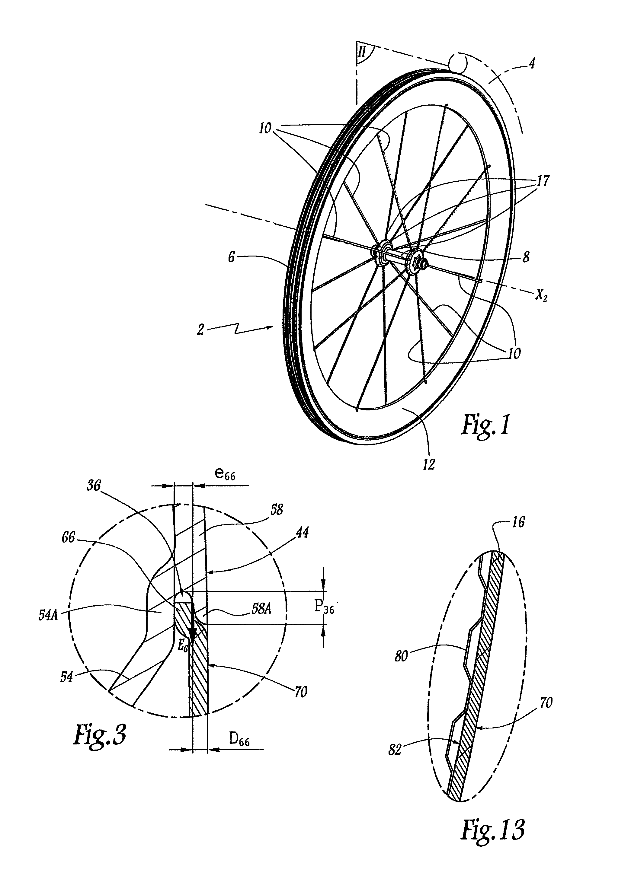
[0122]In the embodiment of FIG. 13, the half-shell 16 is equipped with an inner skin 80 welded locally onto its inner surface 82. This makes it possible to stiffen the half-shell 16 in order to withstand a buckling force that is exerted within this half-shell, between its radially outer edge 66 and its radially inner edge 62, under the effect of the force E6. The inner skin 80 thus constitutes a stiffener for the half-shell 16. In this embodiment, the shell 14 is also equipped with an inner skin 80 forming a stiffener. All the walls of the wheel fairing 12 are therefore provided with a stiffener.

[0123]Other stiffening structures are encompassed within the scope of the invention, such...

third embodiment

[0130]Moreover, the wheel 2 of the third embodiment can be manufactured according to the method depicted in FIGS. 16 and 17. According to this method, the rim 6 is immobilized between two clamping jaws 300 and 301. Each jaw 300 and 301 is equipped with a ramp 302, 303, respectively, inclined with respect to the plane P6, and which ends in the vicinity of the extensions 58A and equivalent of the sides 56 and 58 of the rim 6 which laterally demarcate the grooves 34 and 36.

[0131]The half-shell 14 is positioned on the rim 6 by means of a pusher 310 that moves perpendicular to the plane P6, and in the direction of such plane, as represented by the arrow F310. The pusher 310 can be made of a pliable or flexible material, such as an elastomer, for example, in order to avoid scratching the half-shell 14. The movement F310 of the pusher 310 takes place while the radially outer edge 64 of the half-shell 14 slides against the ramp 302, until the edge 64 engages in the groove 34. That position ...

fourth embodiment

[0134]In the invention shown in FIG. 18, the respective radially inner edges 60 and 62 of the half-shells 14 and 16 are welded by laser, edge surface to edge surface and on a reinforcing ring 84 made of a material similar to that forming the core of the half-shells 14 and 16. The ring 84, which makes the connection between the edges 60 and 62, is arranged in the inner volume V12 of the wheel fairing 12.


PUM

PropertyMeasurementUnit
radial depthaaaaaaaaaa
thicknessaaaaaaaaaa
thicknessaaaaaaaaaa

Abstract

A cycle wheel and methods of manufacture of such a wheel. The cycle wheel has tensioned spokes between a hub and a rim and is equipped with a wheel fairing attached to the rim. The rim is provided with two grooves for receiving two radially outer edges of the wheel fairing, and the rim exerts, in the area of the two grooves, a centripetal force that blocks the radially outer edges of the wheel fairing in the grooves.

Description

CROSS-REFERENCE TO RELATED APPLICATION[0001]The instant application is based upon the French priority Patent Applications No. 09.05551, filed Nov. 19, 2009, and No. 09.5552, filed Nov. 19, 2009, the disclosures of which are hereby incorporated by reference thereto, and the priorities of which are hereby claimed under 35 U.S.C. §119.BACKGROUND[0002]1. Field of the Invention[0003]The invention relates to a cycle wheel with tension spokes between a hub and a rim for receiving a tire, the wheel being equipped with a wheel fairing attached on the rim.[0004]2. Background Information[0005]In the field of cycles, in particular competition bicycles, tension spoke wheels equipped with so-called “aerodynamic” rims for reducing the drag of bicycle wheels and improving the performance of cyclists are known. The rims of these wheels currently are mainly made of a carbon-based composite, which makes them expensive to produce and limits their use in high-end or competition cycles.[0006]The document...

Claims


Application Information

Patent Timeline
Patent Type & Authority Applications(United States)
IPC IPC(8): B60B1/02B23P17/00
CPCB60B1/003B60B7/0006B60B7/0053B60B7/0066Y10T29/49506B60B7/08B60B21/02B60B21/025B60B21/062B60B7/063
Inventor MERCAT, JEAN-PIERREAUGRIS, FABRICE
Owner MAVIC SA
Why Eureka
Try Eureka