EUV Reticle Substrates With High Thermal Conductivity

a technology of reticle substrate and thermal conductivity, which is applied in the direction of printers, instruments, nanotechnology, etc., can solve the problems of significant heating of the reticle, excessively large thermal gradient across the thickness of the reticle, and distort the reticle surface, so as to reduce or eliminate the effect of pattern distortion

Inactive Publication Date: 2011-05-19
ASML HLDG NV
View PDF15 Cites 8 Cited by
  • Summary
  • Abstract
  • Description
  • Claims
  • Application Information

AI Technical Summary

Benefits of technology

[0008]Therefore, what is needed is a reflective reticle for use in EUV lithographic applications that substantially reduces or eliminates pattern distortion due to the a...

Problems solved by technology

Such absorption can lead to significant heating of the reticle, which can distort the reticle surface, in spite of the relatively-low coefficient of thermal expansion of the ULE glass substrate, and introduce errors in the projected image.
Further, even if a back side of such a reflective reticle were optimally cooled, the absorption of EUV radiation could result in an excessively large thermal gradient across a ...

Method used


Image

  • EUV Reticle Substrates With High Thermal Conductivity
  • EUV Reticle Substrates With High Thermal Conductivity
  • EUV Reticle Substrates With High Thermal Conductivity

Examples


Embodiment Construction

I. Overview

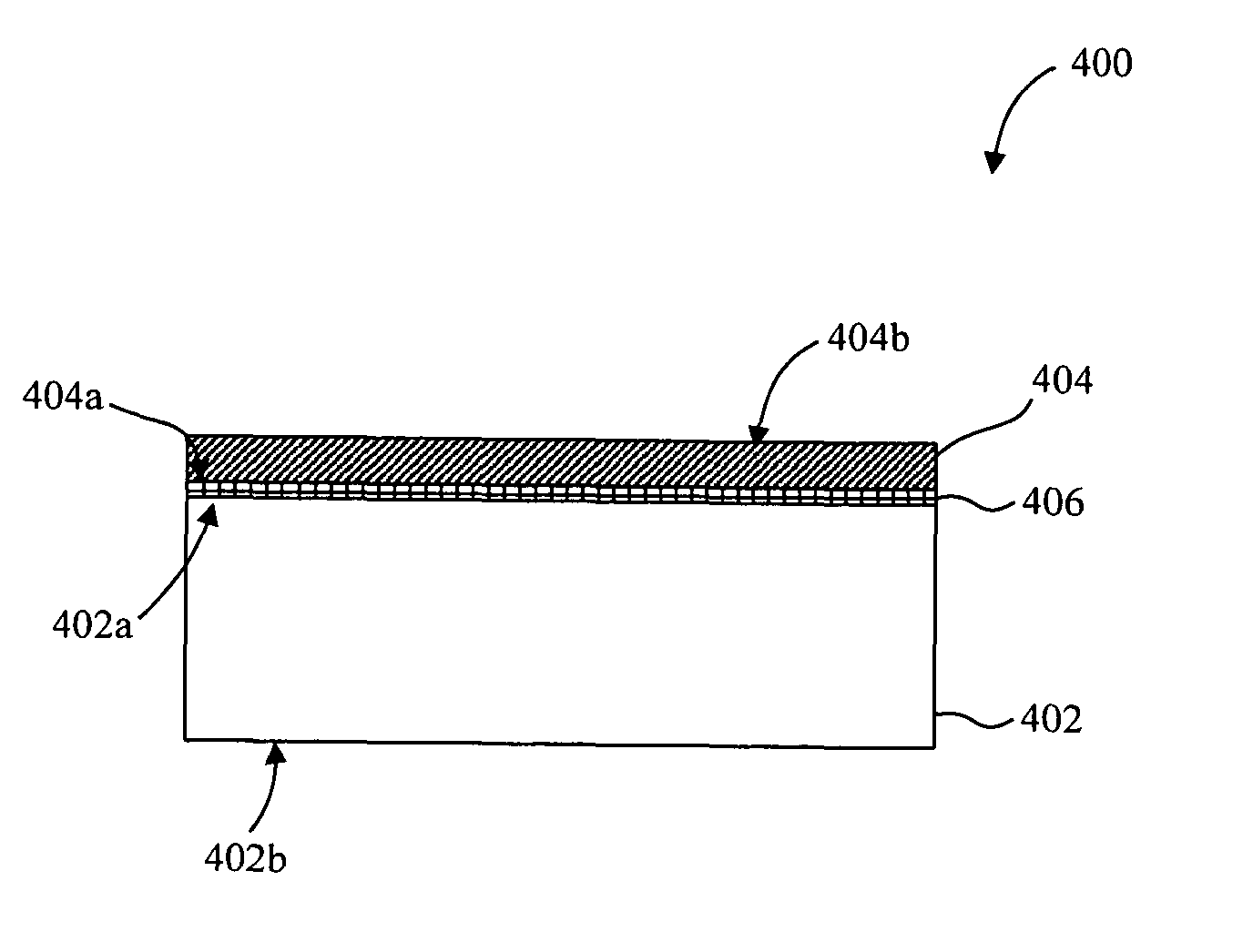
[0023]The present invention is directed to reticles that include substrates having high thermal conductivities, and in particular, to substrates for EUV reflective reticles having high thermal conductivities. This specification discloses one or more embodiments that incorporate the features of this invention. The disclosed embodiment(s) merely exemplify the invention. The scope of the invention is not limited to the disclosed embodiment(s). The invention is defined by the claims appended hereto.

[0024]The embodiment(s) described, and references in the specification to “one embodiment”, “an embodiment”, “an example embodiment”, etc., indicate that the embodiment(s) described may include a particular feature, structure, or characteristic, but every embodiment may not necessarily include the particular feature, structure, or characteristic. Moreover, such phrases are not necessarily referring to the same embodiment. Further, when a particular feature, structure, or characteri...


PUM


Abstract

A reflective reticle substantially reduces or eliminates pattern distortion that results from the absorption of EUV radiation while maintaining a reticle thickness consistent with industry standards. The reflective reticle includes a layer of ultra-low expansion (ULE) glass and a substrate of Cordierite having a thermal conductivity substantially larger than that of ULE glass. An aluminum layer is disposed onto a first surface of the ULE glass and a second surface of the ULE glass is polished to be substantially flat and defect-free. The Cordierite substrate can be directly bonded to the aluminum layer using anodic bonding to form the reflective reticle. Alternatively, a first surface of an intermediate Zerodur layer can be bonded to the aluminum layer, and a second aluminum layer can be used to anodically bond the Cordierite substrate to a second surface of the Zerodur layer, thereby forming the reflective reticle.

Description

BACKGROUND[0001]1. Field of the Invention[0002]The present invention relates to patterning devices for use in lithographic apparatus.[0003]2. Related Art[0004]Lithography is widely recognized as a key process in manufacturing integrated circuits (ICs) as well as other devices and / or structures. A lithographic apparatus is a machine, used during lithography, which applies a desired pattern onto a substrate, such as onto a target portion of the substrate. During manufacture of ICs with a lithographic apparatus, a patterning device (which is alternatively referred to as a mask or a reticle) generates a circuit pattern to be formed on an individual layer in an IC. This pattern may be transferred onto the target portion (e.g., including part of, one, or several dies) on the substrate (e.g., a silicon wafer). Transfer of the pattern is typically via imaging onto a layer of radiation-sensitive material (e.g., resist) provided on the substrate. In general, a single substrate contains a netw...

Claims


Application Information

Patent Timeline
IPC IPC(8): G03B27/54G03F1/00G03F1/22G03F1/62
CPCB82Y10/00G03F7/70891G03F1/24B82Y40/00G03F1/22G03F1/60H01L21/027
Inventor WILKLOW, RONALD A.NELSON, MICHAEL L.PERRY, MICHAEL
Owner ASML HLDG NV
Why Eureka
Try Eureka