Auxiliary vacuum device for a central vacuum cleaning system

a vacuum cleaning and auxiliary technology, applied in the field of central vacuum cleaning system, can solve the problems of high cumbersomeness, limited power of auxiliary devices, and long hose length, and achieve the effect of reducing accidental activation of devices and simple construction and design

Inactive Publication Date: 2011-05-26
WIDMAR
View PDF24 Cites 27 Cited by
  • Summary
  • Abstract
  • Description
  • Claims
  • Application Information

AI Technical Summary

Benefits of technology

[0010]An advantage of the present invention is that the switching mechanism for deactivating and activating the device is of simple construction and design.
[0011]A further advantage of the present invention is that the switching mechanism uses a single lever or switch for ensuring both automatic deactivation of the device when the probe is installed in the docking station and enabling activation of the device when the probe is removed from the docking station.
[0012]Yet another advantage of the present invention is that the switching mechanism is designed such that, when the probe is removed from the docking station, accidental activation of the device is discouraged.
[0013]According to an aspect of the invention, there is provided an auxiliary vacuum device for a central vacuum cleaning system for premises defining areas of occupancy, the system including an electrically powered vacuum generating unit, a system network of piping extending throughout the premises and terminating in at least one inlet formed in one of the walls defining at least some of the areas of occupancy, the device comprising a housing adapted for installation externally of the wall at a mounting plate of the system network, the mounting plate disposed on the wall with the inlet extending through the mounting plate, the housing being provided with a port for communication with the inlet, a connector exterior to the housing, a pipe extending within the housing from the port to the connector, a flexible hose connected to the port and extending externally from the housing, a cleaning tool mounting probe provided on the hose distal the connector a docking station for parking of the probe therein and extending adjacently alongside a proximal side of the housing, and a switch mechanism having a pivotally mounted lever extending within the housing and outside of the housing into the docking station, the lever being pivotable, when the probe is disengaged from the docking station, in a first direction into a activated position therefor to place the switch mechanism in an activated configuration in which the device is activated and in a generally opposed second direction into a deactivated position therefor to place the switch mechanism in a deactivated configuration in which the device is deactivated, the probe moving the lever in the second direction to place the switch mechanism into the deactivated configuration when the probe is parked in the docking station and holding the switch mechanism in the deactivated configuration when parked in the docking station.
[0014]Other objects and advantages of the present invention will become apparent from a careful reading of the detailed description provided herein, with appropriate reference to the accompanying drawings.

Problems solved by technology

Naturally, there are available small portable vacuum cleaners operable independently of the central vacuum system, which may easily be transported manually from location to location within domestic or commercial premises, but generally their power is restricted by the need to afford portability.
The length of the hose makes laborious the task of vacuuming in view of the need to carry such an unwieldy and relatively heavy mass of hose between stations.
A disadvantage of such a system is it always requires the opening of a cabinet door before reaching the cleaning tool, and the door remains open during operation of the system, which might be highly cumbersome.
Unfortunately, the switch mechanism enabling the on / off functionality for the probe and docking station and the separate on / off switch is unnecessarily complex and cumbersome in that it requires a substantial number of cams, guide arms, stub shafts, and the like to provide the aforementioned functionality.

Method used


Image

  • Auxiliary vacuum device for a central vacuum cleaning system
  • Auxiliary vacuum device for a central vacuum cleaning system
  • Auxiliary vacuum device for a central vacuum cleaning system

Examples


Embodiment Construction

[0020]With reference to the annexed drawings the preferred embodiment of the present invention will be herein described for indicative purpose and by no means as of limitation.

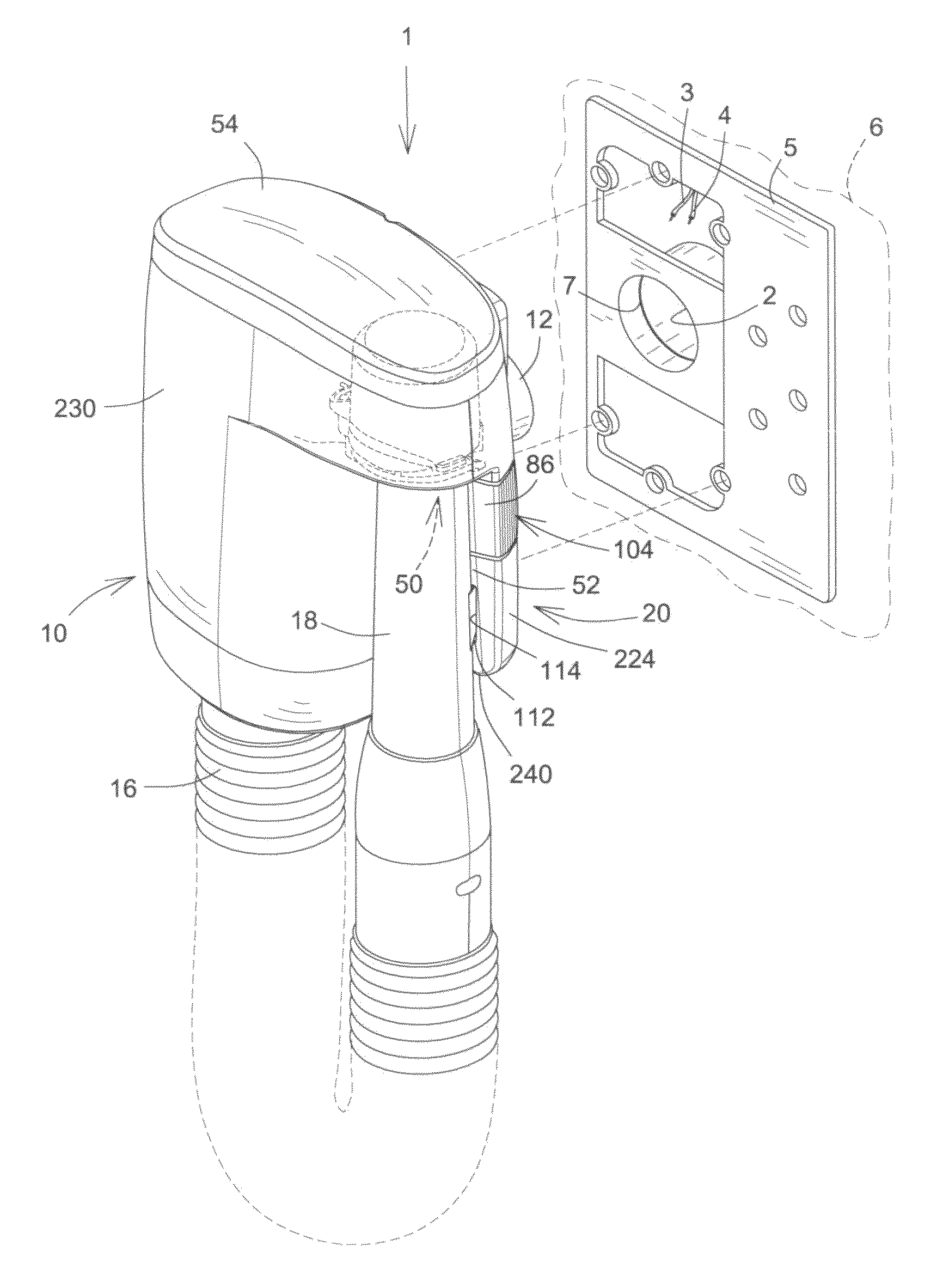
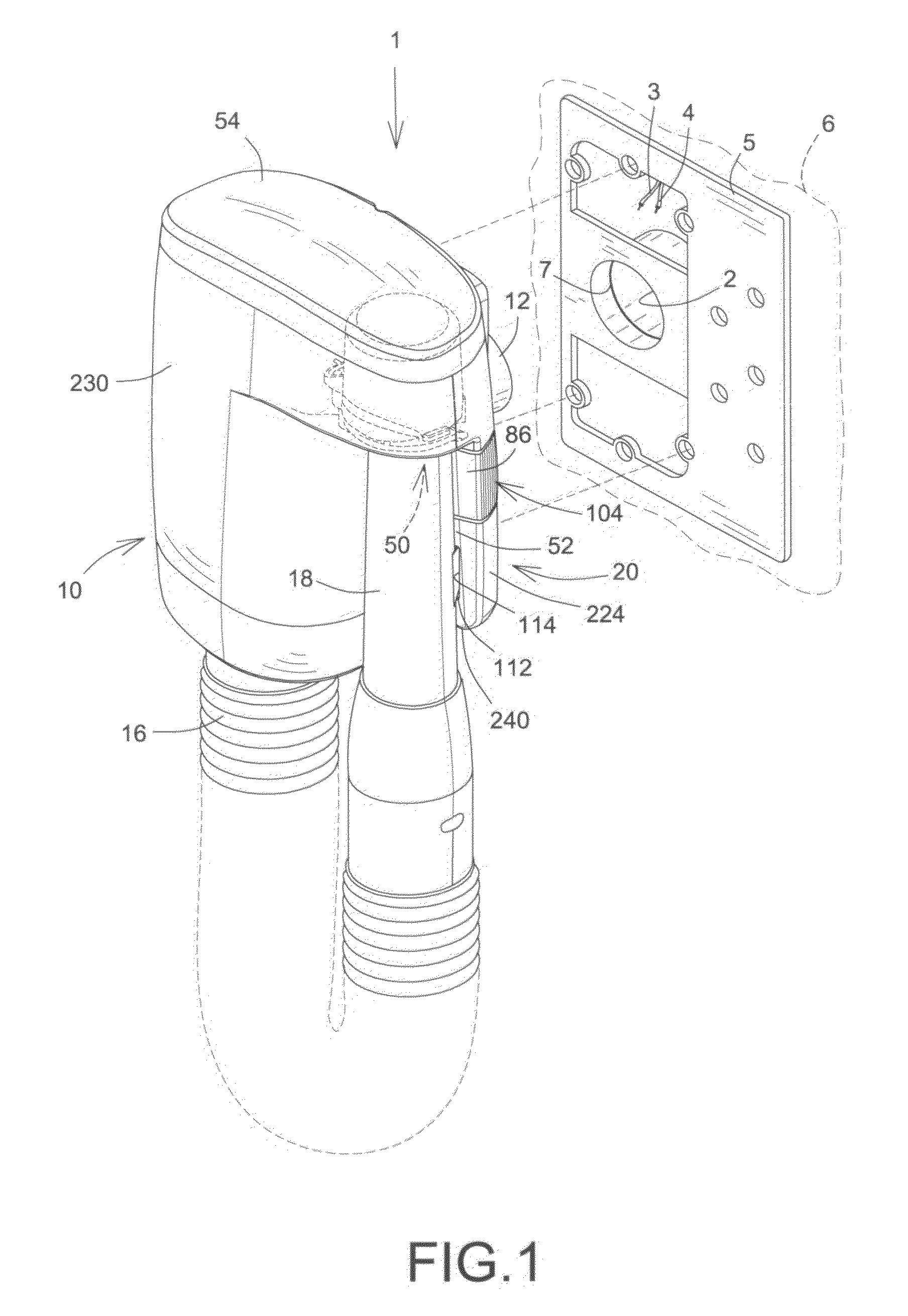
[0021]In FIG. 1, there is illustrated an auxiliary vacuum device, shown generally as 1, which is mountable on a mounting plate 5. Mounting plate 5 incorporates an inlet opening 2 of a central vacuum cleaning system (not shown) which incorporates an electrically powered vacuum generating unit, including a motor, for generating a vacuum. The operation of vacuum generating unit is controlled by the device 1 in the manner hereinafter defined. Suitable low voltage electrical wires 3, 4, connected to an electrical power supply and to the electrically powered vacuum generating unit, are provided and protrude from a rear aperture 300 in the mounting plate 5 which is installed in or on a wall 6 of the area of occupancy or premises in which the central vacuum cleaning system is installed.

[0022]Referring now to FIGS. 1, ...


PUM


Abstract

An auxiliary vacuum device for a central vacuum cleaning system is location specific and comprises housing mountable externally on an inlet of a mounting plate of the system, a dedicated flexible concertina hose is provided on the device and a cleaning tool mounting probe is registrable with a docking station. When the probe is removed from the docking station, a lever may be moved in first and second directions to selectively activate and deactivate the motor of the central vacuum cleaning system and the device. When the probe is parked in the docking station the probe moves the lever in one of the directions and holds the lever in a deactivated configuration, thus deactivating the motor and the device and preventing activation thereof.

Description

FIELD OF THE INVENTION[0001]The present invention relates in general to a central vacuum cleaning system and more particularly to an auxiliary device for attachment to the central vacuum cleaning system.BACKGROUND OF THE INVENTION[0002]Central vacuum cleaning systems are well known and are to be found in domestic and commercial premises to provide a centralized cleaning regime based on the vacuum cleaner principle to minimize the carriage of conventional equipment from place to place. Naturally, there are available small portable vacuum cleaners operable independently of the central vacuum system, which may easily be transported manually from location to location within domestic or commercial premises, but generally their power is restricted by the need to afford portability.[0003]It is normal in a central vacuum cleaning system, for example as deployed in a condominium, to site a few strategically placed connection stations, coupled in a circuit to a central vacuum generating unit,...

Claims


Application Information

Patent Timeline
Patent Type & Authority Applications(United States)
IPC IPC(8): A47L5/38
CPCA47L5/38
Inventor MARCIL, CHRISTIANWIDMER, URSLAPALME, AMIELDAVID, SYLVAINGELINAS, FRANCOIS
Owner WIDMAR
Why Eureka
Try Eureka