Circulation type water purifier

a water purifier and circular type technology, applied in the direction of filtration separation, multi-stage water/sewage treatment, separation process, etc., can solve the problems of cost and maintenance, pollution is not removed, and the connection pipes and other parts of the water purifier are still sanitary problems, so as to prolong the life of the pump and save power consumption , the effect of prolonging the time of filter replacemen

Inactive Publication Date: 2011-05-26
APPL TECH CORP
View PDF3 Cites 36 Cited by
  • Summary
  • Abstract
  • Description
  • Claims
  • Application Information

AI Technical Summary

Benefits of technology

[0022]As described above, according to the present invention, water is circulated by allowing a pump to be operated by a microcomputer depending on the amount of water used if necessary, so that power consumption can be saved, and accordingly, the lifetime of the pump can be extended. Since biofilm is not formed in a clean water filter while water is periodically circulated, a period of replacing filters can be extended, and accordingly, the maintenance cost of the water purifier can be saved. Since a water tank is not separately installed, space utilization can be improved.

Problems solved by technology

However, since only the cleansing of the interiors of the storage tank and the cold / hot water supply tanks and the replacement of filters are performed, problems for sanitary reasons with respect to connection pipes and other parts in the water purifier still remain.
Further, although the filters are periodically replaced, the pollutants are not removed without cleansing or replacing a connection pipe to the storage tank in which water is stored from the filters and other connection pipes.
Furthermore, problems of cost and maintenance are proposed to solve them.
In addition, if a certain time (three hours) elapses in the state that clean water does not flow but remain inside the water purifier, bacteria (hereinafter, referred to as “microbes”) harmful to human bodies are reproduced, and the number of microbes increases by geometric progression.
Therefore, the filters mainly cause pollution of the water purifier.
The pollution of the water purifier results in a problem for sanitary reasons.
However, it is difficult that a water level sensor is normally operated due to vibrations of water at a place such as a vessel, and an overload is applied to a circulation pump for circulating water due to malfunction of the sensor.

Method used


Image

  • Circulation type water purifier
  • Circulation type water purifier
  • Circulation type water purifier

Examples


first embodiment

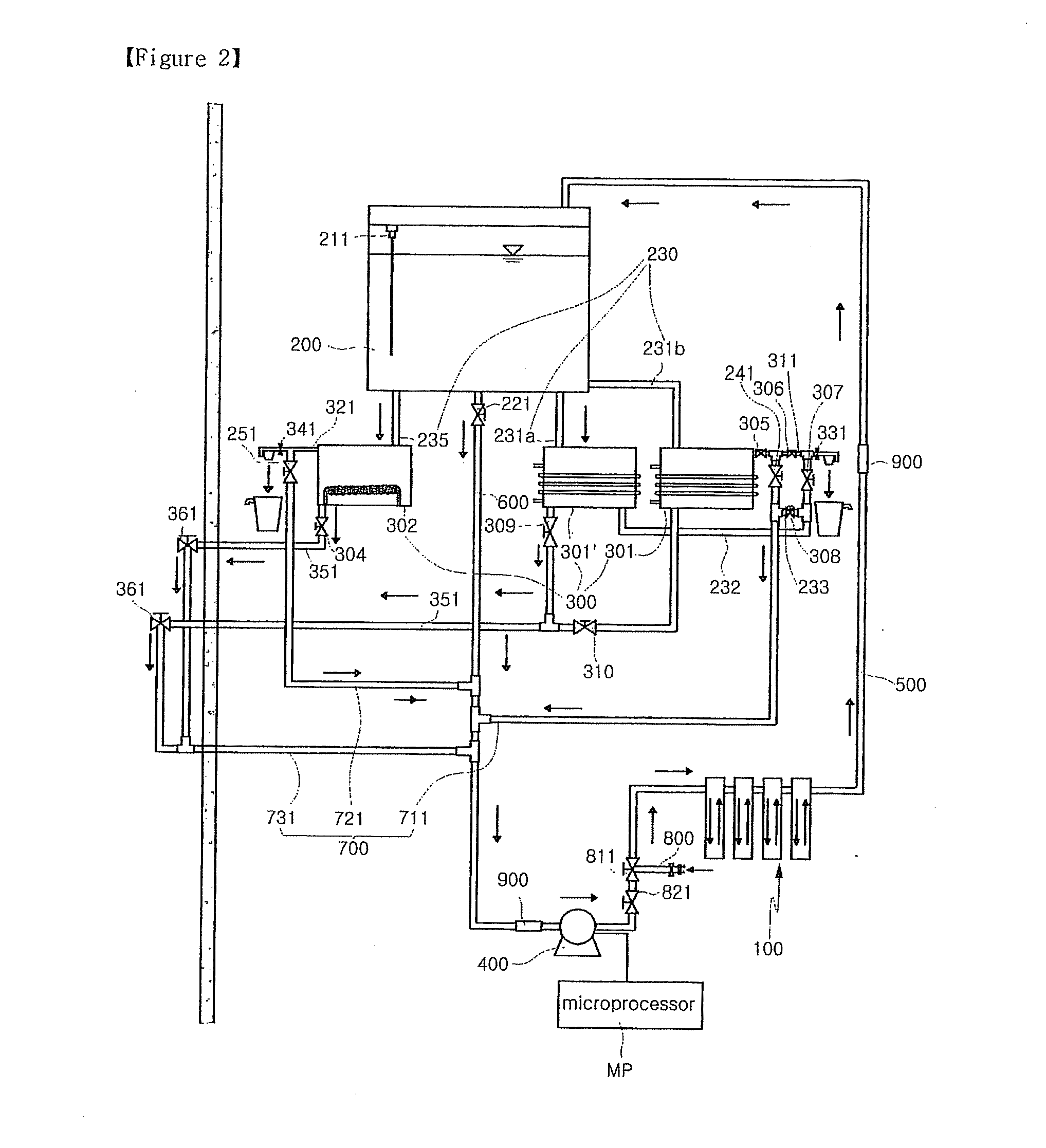
First Faucet Direct-Connection Type (See FIG. 2)

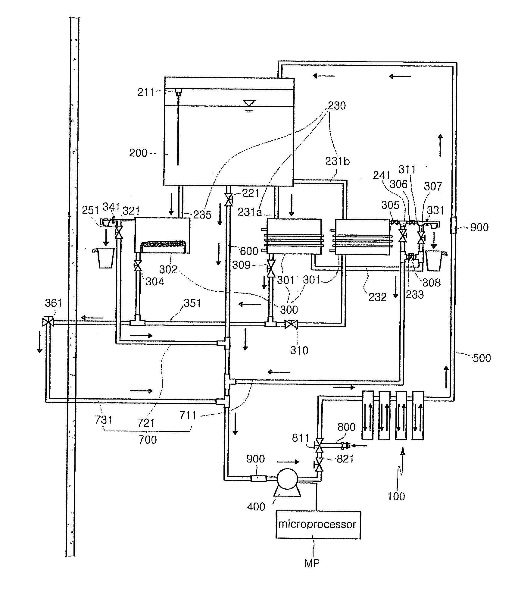
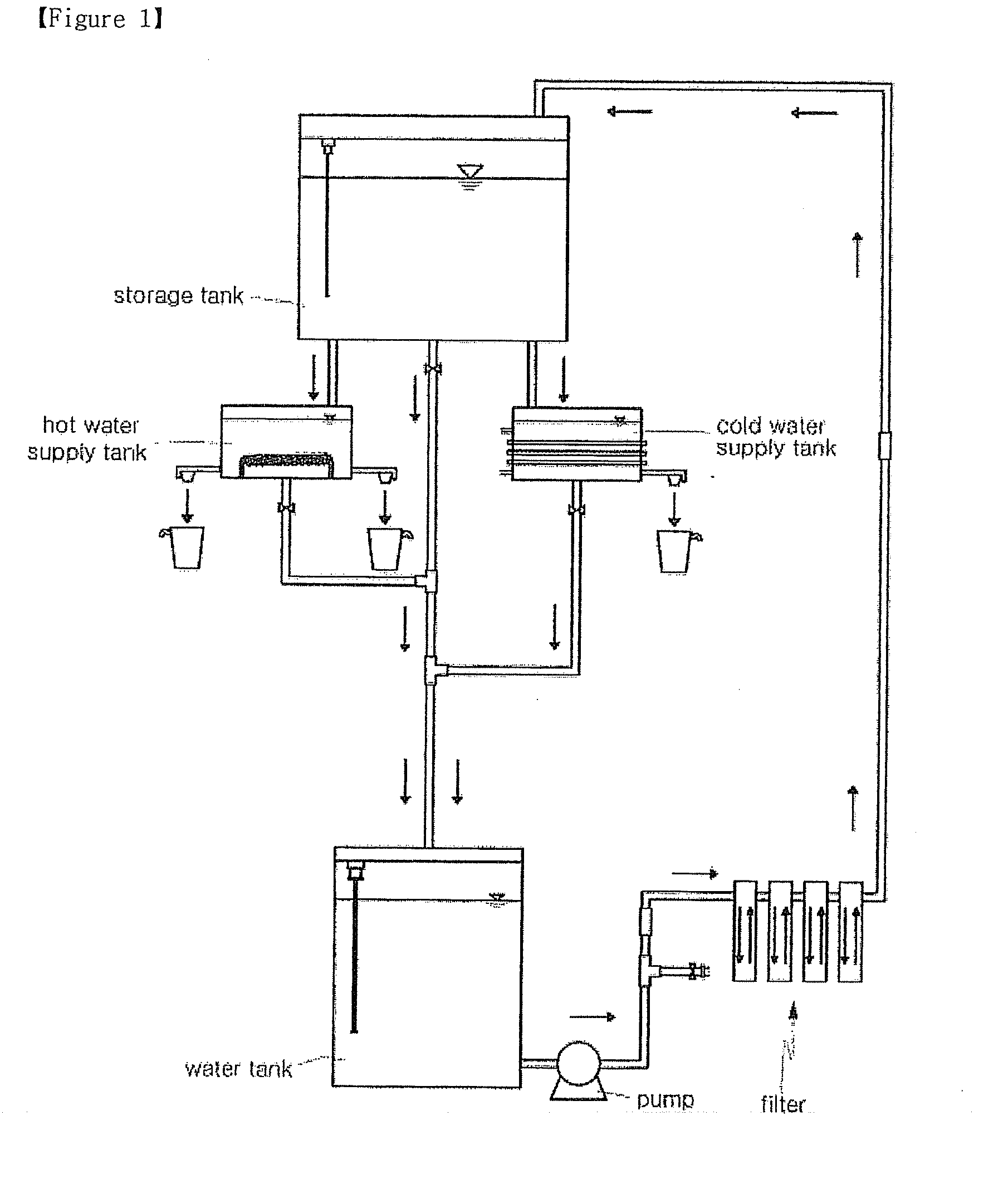
[0088]1) Water is flowed into the second circulation pipe 600 through the faucet direct-connection pipe 800.

[0089]2) The flowed water is flowed into the clean water filter 100.

[0090]3) The water filtered by the clean water filter 100 is flowed into the storage tank 200 along the first circulation pipe 500.

[0091]4) The water in the storage tank 200 is flowed into the cold water supply tank 301, the auxiliary cold water supply tank 301′ and the hot water supply tank 302 along the first auxiliary connection pipes 231a and 231b and the second auxiliary connection pipe 235.

[0092]5) The water in the cold water supply tank 301, the auxiliary cold water supply tank 301′ and the hot water supply tank 302 is drained through the cold and hot water outlets 311 and 321 so as to supply drinking water.

[0093]6) The sensors 331 and 341 sense information on the drinking water and transfer the sensed information to the microcomputer MP.

[0094]7) The water...

second embodiment

[0150]As shown in FIG. 13, the second embodiment has a structure in which the third and fifth open / close valves 306 and 308 and the second auxiliary water supply connection pipe 233 are omitted in the configuration of the first embodiment. Therefore, the circulation structure of water when the water in the cold water supply tank 301 and the auxiliary cold water supply tank 301′ is alternately circulated is different from that when cooled water is drained (in the following description, only the valves 306 and 308 and the connection pipe 233 are omitted for convenience of illustration).

[0151]That is, when the water in the cold water supply tank 301 is circulated, the second and seventh open / close valves 305 and 310 and the cold water open / close valve 241 are opened, and the fourth and sixth open / close valves 307 and 309 are closed, as shown in FIG. 15.

[0152]When the water in the auxiliary cold water supply tank 301′ is circulated, the fourth and sixth open / close valves 307 and 309 and...


PUM

PropertyMeasurementUnit
circulation timeaaaaaaaaaa
timeaaaaaaaaaa
period of timeaaaaaaaaaa

Abstract

There is provided a circulation type water purifier which maximally prevents production of bacteria and microbes by periodically circulating water in the water purifier, and improves lifetime and power saving of a pump by varying the number of circulation times depending on an amount of water used. The circulation type water purifier includes a clean water filter; a storage tank in which water purified through the clean water filter is stored; a cold/hot water supply tank cooling and heating the water supplied from the storage tank to drain the cooled and heated water to respective drain outlets; a drain pipe 351 connected to the cold/hot water supply tank to drain the water in the cold/hot water supply tank when cleansing the interior of the cold/hot water supply tank; a pump 400 periodically circulating water at every circulation time under a control of a microcomputer; a circulation pipe connecting the clean water filter, the cold/hot water supply tank, the drain pipe and the pump, the circulation pipe including a first circulation pipe connecting the clean water filter and the storage tank, a first auxiliary circulation pipe connecting the storage tank and the cold/hot water supply tank, a second circulation pipe connecting the storage tank and the clean water filter, and a second auxiliary circulation pipe connecting the cold/hot water supply tank and the second circulation pipe! and a sterilizer installed to the circulation pipe to sterilize water flowed into the circulation pipe.

Description

TECHNICAL FIELD[0001]The present invention relates to a circulation type water purifier, and more particularly, to a circulation type water purifier which maximally prevents production of bacteria and microbes and formation of slime and biofilm by periodically circulating water in the water purifier, and improves efficiency and power saving of a pump by varying the number of circulation times depending on an amount of water used.BACKGROUND ART[0002]In general, water purifiers are classified into an air collection type water purifier used by collecting moisture from the air, a faucet direct-connection type water purifier connected to a waterworks pipe, and a spring water supply type water purifier used by directly supplying purified water thereto. Such purifiers are selectively used depending on conditions of a place and require continuous maintenance so that a user drinks sanitized water in contaminated environment.[0003]A method of periodically cleaning the interior of a water puri...

Claims


Application Information

Patent Timeline
Patent Type & Authority Applications(United States)
IPC IPC(8): C02F9/08B01D29/60
CPCB67D1/0004C02F2103/04B67D1/0857B67D1/0895B67D2210/00002B67D2210/0001C02F1/001C02F1/283C02F1/32C02F1/44C02F1/505C02F1/78C02F9/005C02F2209/005C02F2209/42C02F2301/046C02F2305/10C02F2307/10B67D1/0009C02F9/20B01D35/00
Inventor KIM, JAEKYEONG
Owner APPL TECH CORP
Why Eureka
Try Eureka