Vehicle disk motor with movable magnet poles

a disk motor and magnet pole technology, applied in the direction of magnetic circuit rotating parts, magnetic circuit shapes/forms/construction, electric devices, etc., can solve the problems of unoptimized disk motor efficiency and unduly limited range of associated vehicles, so as to reduce the retarding effect and increase the efficiency of disk motors

Active Publication Date: 2011-05-26
SILICON VALLEY MICRO MCORP
View PDF3 Cites 25 Cited by
  • Summary
  • Abstract
  • Description
  • Claims
  • Application Information

AI Technical Summary

Benefits of technology

[0007]The invention comprises a disk motor pole piece design which substantially reduces the retarding effect caused by the magnetic field interaction between the permanent magnets mounted on the rotor and the electromagnet pole pieces of the deactivated electromagnets in a disk motor, and thereby raises the efficiency of the disk motor.
[0023]The invention has wide application to a variety of vehicles, such as an automobile, a bicycle, a motorcycle, and the like. Disk motors provided with pole pieces movably mounted on the stator plates are capable of more efficient operation than disk motors with fixed pole pieces when their associated coils are selectively driven by power control signals. Specifically, by affording automatic retraction of the pole pieces when the associated coil is not activated, the air gap between the face of the pole piece and the face of any confronting rotor-mounted permanent magnet is substantially increased, which in turn substantially reduces any magnetic interaction between the pole piece and the permanent magnet and thus substantially reduces any retarding force on the rotor. However, when any given coil is activated, the air gap between the face of the pole piece and the face of any confronting rotor-mounted permanent magnet is reduced to a minimum, thereby promoting magnetic interaction between the pole piece and the permanent magnet. Consequently, even greater battery life can be achieved in a battery-powered disk motor incorporating the invention.

Problems solved by technology

This excessive use of battery power unduly limits the range of the associated vehicle and thus the performance of known brushless D.C. motor vehicle propulsion systems.
As a result, the efficiency of the disk motor is less than optimal.

Method used


Image

  • Vehicle disk motor with movable magnet poles
  • Vehicle disk motor with movable magnet poles
  • Vehicle disk motor with movable magnet poles

Examples


Embodiment Construction

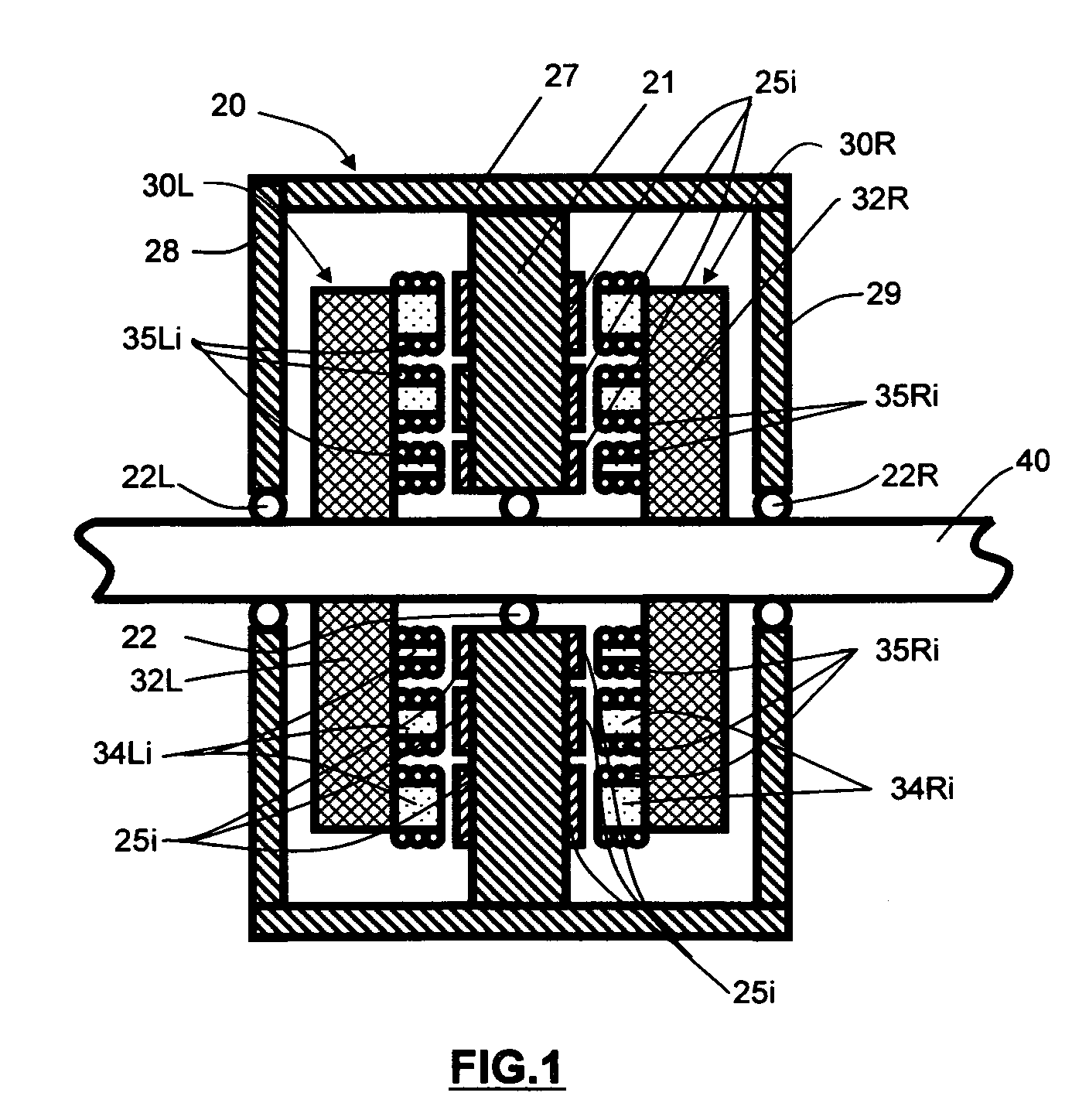
[0040]Turning now to the drawings, FIG. 1 is a sectional view taken along the longitudinal axis of a disk motor having a single rotor and a pair of flanking stators. As seen in this Fig., the disk motor includes a disk rotor assembly 20 and a pair of stator assemblies 30L, 30R. Disk rotor assembly 20 comprises a central disk member 21 rotatably mounted by means of a standard low friction bearing 22 to a mounting shaft 40. Shaft 40 is secured to the frame of a vehicle (not shown) and serves as the mounting support for the disk motor. Shaft 40 may comprise an axle stub of an automobile, for example. Secured to opposing faces of disk member 21 are a plurality of permanent magnets 25i. Disk member 21 is fabricated from a non-magnetic material, such as Delrin, Nylon, aluminum, or any other relatively stiff non-magnetic material. Permanent magnets 25i are secured to disk member 21 using any one of a number of known techniques, such as adhesive bonding with a secure bonding adhesive (e.g. ...


PUM


Abstract

A brushless D.C. disk motor has one or more disk rotor assemblies and pairs of stator assemblies for each rotor assembly. Each disk rotor assembly has a disk and a plurality of permanent magnets distributed along two or more circular paths in the disk inboard of the peripheral edge of the rotor. Each stator assembly has a plurality of pole pieces and coils distributed along a mounting plate in corresponding circular paths. The disk is rotatably mounted to a support member; while the stator sub-assemblies are fixed to the support member. The coils are selectively activated by commutated power control signals generated in response to a vehicle condition parameter, such as vehicle speed or disk motor load, to optimize power drain from the source of electrical power in accordance with the value of the vehicle condition parameter. The stator assembly pole pieces are movably mounted on the stator mounting plate to improve motor efficiency.

Description

BACKGROUND OF THE INVENTION[0001]This invention relates to brushless D.C. motors used for the propulsion of vehicles. More particularly, this invention relates to a brushless D.C. vehicle propulsion motor with a more efficient design using movable magnet poles.[0002]Brushless D.C. vehicle propulsion motors are known and have been used for the propulsion of many different types of vehicles, such as bicycles, motorcycles, autos, and small trucks. A typical motor design has a rotor and a stator. The rotor is fixedly attached to the vehicle wheel for rotation therewith; the stator is attached to a vehicle stationary member, such as the fork of a bicycle or motorcycle frame. A specific type of brushless D.C. motor is a disk motor. In a disk motor, both the rotor and the stator typically comprise disks having circular geometry, with the rotor disk being rotationally arranged between two flanking stator disks. The rotor disk usually carries a plurality of permanent magnets mounted along a ...

Claims


Application Information

Patent Timeline
Patent Type & Authority Applications(United States)
IPC IPC(8): H02K21/24H02K1/18B60K1/00
CPCB60L11/1803B60L2220/44Y02T10/7005H02K21/24Y02T10/641H02K21/026B60L2200/12B60L2220/16B60L2240/12B60L2240/429B60L50/51Y02T10/64Y02T10/70
Inventor ZHU, SHENGBOHUANG, SU SHIONG
Owner SILICON VALLEY MICRO MCORP
Why Eureka
Try Eureka