Plasma processing apparatus and plasma processing method

Active Publication Date: 2011-05-26
TOKYO ELECTRON LTD +1
View PDF7 Cites 210 Cited by
  • Summary
  • Abstract
  • Description
  • Claims
  • Application Information

AI Technical Summary

Benefits of technology

[0027]As described above, according to the present invention, characteristic impedances of

Problems solved by technology

In the plasma processing apparatus having a structure wherein a gas passage is formed on a ceiling surface of the processing container and the gas is introduced into the processing container from the ceiling surface by using the ceiling surface as a shower plate, a thickness of a coaxial waveguide is difficult to be increased since a gas passage has to be formed in a location that does not interfere with the coaxial waveguide for transm

Method used


Image

  • Plasma processing apparatus and plasma processing method
  • Plasma processing apparatus and plasma processing method
  • Plasma processing apparatus and plasma processing method

Examples


embodiment 1

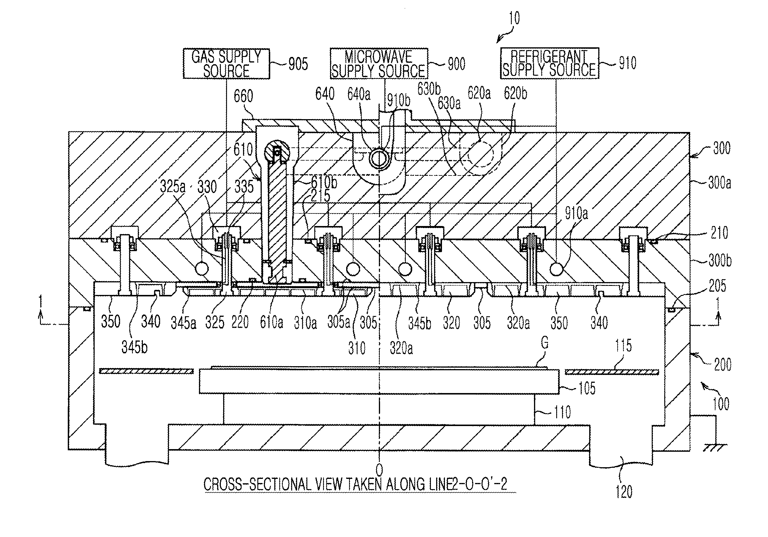
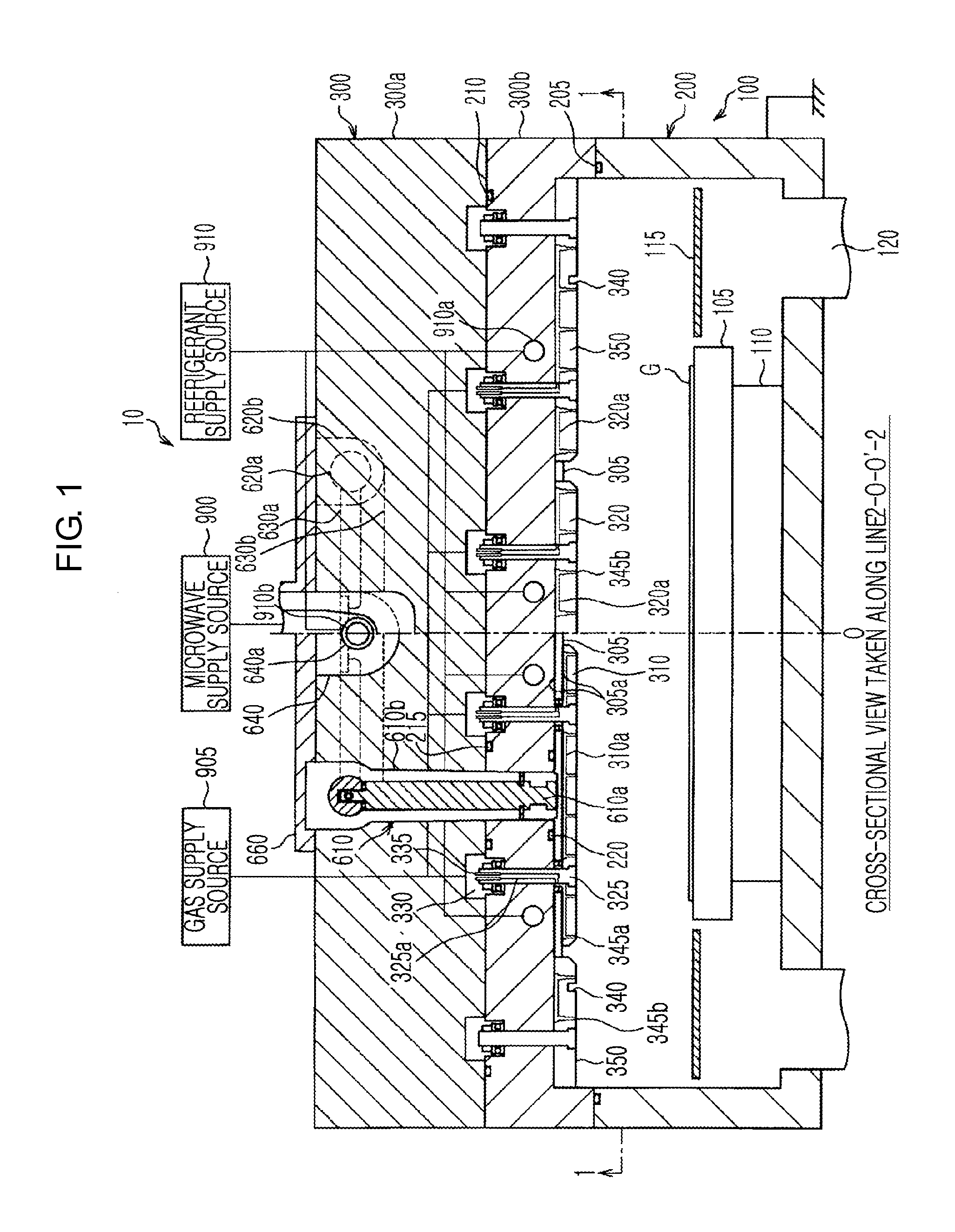
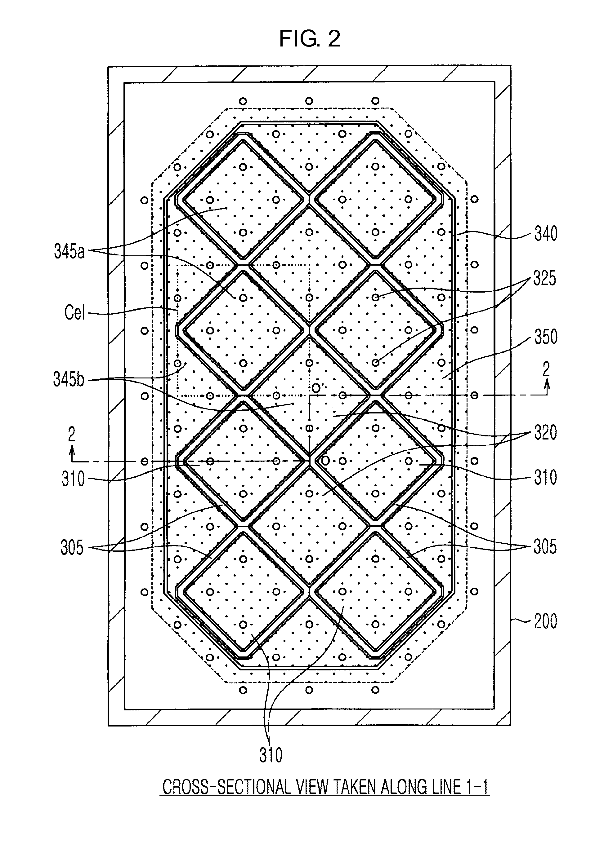
[0041]A structure of a microwave plasma processing apparatus according to an embodiment 1 of the present invention will now be described with reference to FIGS. 1 and 2. FIG. 1 is a longitudinal-sectional view of a microwave plasma processing apparatus 10 according to the present embodiment. FIG. 1 is a cross-sectional view taken along a line 2-O-O′-2 of FIG. 2. FIG. 2 shows a ceiling surface of the present apparatus 10, and is cross-sectional view taken along a line 1-1 of FIG. 1.

[0042](Outline of Microwave Plasma Processing Apparatus)

[0043]As shown in FIG. 1, the microwave plasma processing apparatus 10 includes a processing container 100 for plasma-processing a glass substrate (hereinafter, referred to as a substrate G). The processing container 100 includes a container body 200 and a lid 300. The container body 200 has a cube shape having an opened top and a closed bottom, wherein the opened top is closed by the lid 300. The lid 300 is formed of an upper lid 300a and a lower lid...

embodiment 2

[0096]Fixation of the inner conductor 610a of the first coaxial waveguide and coaxial waveguide matching, according to a embodiment 2 of the present invention will now be described with reference to FIG. 10. FIG. 10 corresponds to FIG. 3 that is used to describe the embodiment 1. The embodiment 2 is different from the embodiment 1 in the structure of the connecting portion Dc, and that a dielectric ring is disposed near a dielectric plate. Accordingly, the differences will be mainly described, and other descriptions will be omitted.

[0097]In the connecting portion Dc according to the embodiment 2, the dielectric rod 720 is inserted into the horizontal hole 620a3 of the inner conductor 620a of the second coaxial waveguide, and accordingly, the inner conductor 620a is supported by the outer conductor 620b. Meanwhile in the present embodiment, since the dielectric rod 720 does not penetrate through the inner conductor 610a of the first coaxial waveguide, it has no function for preventin...

embodiment 3

[0102]Fixation of the inner conductor 610a of the first coaxial waveguide and coaxial waveguide matching, according to a embodiment 3 of the present invention will now be described with reference to FIG. 11. FIG. 11 corresponds to FIG. 3 that is used to describe the embodiment 1 and FIG. 10 that is used to describe the embodiment 2. The embodiment 3 is different from the embodiment 2 in the structure of the connecting portion Dc. Accordingly, the differences will be mainly described, and other descriptions will be omitted.

[0103]In the connecting portion Dc according to the embodiment 3, the recess portion 610a4 is formed on the periphery of the rod 610a1 of the inner conductor 610a, and a flat spring 610a5 is formed an outer side of the recess portion 610a4. A shield spiral is not disposed on a catching portion. The flat spring 610a5 is an example of a connecting member electrically connecting the inner conductors 610a and 620a.

[0104]The metal spring 730 is disposed on the recess p...


PUM

PropertyMeasurementUnit
Electric impedanceaaaaaaaaaa

Abstract

Provided is a plasma processing apparatus having a coaxial waveguide structure in which characteristic impedance of an input side and characteristic impedance of an output side are different. A microwave plasma processing apparatus, which plasma-processes a substrate by exciting a gas by using a microwave, includes: a processing container; a microwave source, which outputs a microwave, a first coaxial waveguide, which transmits the microwave output from the microwave source; and a dielectric plate, which is adjacent to the first coaxial waveguide while facing an inner side of the processing container, and emits the microwave transmitted from the first coaxial waveguide into the processing container. A thickness ratio between an inner conductor and an outer conductor of the first coaxial waveguide is not uniform along a longitudinal direction.

Description

TECHNICAL FIELD[0001]The present invention relates to a plasma processing apparatus and a plasma processing method, wherein plasma is generated by using electromagnetic waves and a plasma process is performed on an object to be processed, and more particularly, to impedance matching of a transmission path.BACKGROUND ART[0002]In a microwave plasma processing apparatus, in order to generate plasma by exciting a gas, a desired microwave as energy for ionizing or dissociating the gas is transmitted to a transmission path, and is emitted into a processing container. In the plasma processing apparatus having a structure wherein a gas passage is formed on a ceiling surface of the processing container and the gas is introduced into the processing container from the ceiling surface by using the ceiling surface as a shower plate, a thickness of a coaxial waveguide is difficult to be increased since a gas passage has to be formed in a location that does not interfere with the coaxial waveguide...

Claims


Application Information

Patent Timeline
IPC IPC(8): H05H1/24
CPCH01J37/32192H01J37/32229H01J37/32211
Inventor HIRAYAMA, MASAKIOHMI
Owner TOKYO ELECTRON LTD
Why Eureka
Try Eureka