
Switch with common-mode choke

Active Publication Date: 2011-05-26
COGNIPOWER
View PDF2 Cites 6 Cited by
  • Summary
  • Abstract
  • Description
  • Claims
  • Application Information

AI Technical Summary

Benefits of technology

[0006]In the present invention, switch drive pulses, instead of being applied to one or more transformers, are applied to a common-mode choke. These pulses are thereby level-shifted to a high-side voltage to drive a high-side switch. Since the pulses to drive an inherently bistable switch may be made relatively short, and the common-mode choke needs to be connected across the common-mode voltage during the pulses only, the common mode choke has plenty of time to be magnetically reset by convenient circuitry. With an inherently bistable switch, the inductance of the common-mode choke may be made very small. With larger common-mode choke inductances, level-shifting for driving non-inherently-bistable switches may performed. Additionally, since the magnetic field reset occurs largely in the common-mode voltage, and is largely absent from the differential voltage of the common-mode choke, substantially no reset disturbance is applied to the driven switch. According to this invention, a single magnetic device suffices to convey both ON and OFF pulses to the driven switch, and no floating drive supply is needed, yielding excellent timing integrity with great simplicity.

Problems solved by technology

This method does not require a high-side enhancement supply, but is relatively slow, limiting its utility to power-converters operating below a few tens of KHz.
Sometimes opto-couplers are employed to convey control signals to high-side switches, but these usually require a floating high-side supply and also are limited in speed and timing integrity.
With these, good timing integrity can be obtained, but resetting their magnetizing currents incurs either the penalty of significant recovery time or of handling high flyback voltages.
However, doing so requires extra circuitry to reconstruct such pulses to the original control waveform and drive circuitry for the switch, in addition to a high-side power supply for said circuitry.
However the time and / or the circuitry required to reset the capacitor is often an unacceptable burden.
P-channel devices are generally either less conductive or slower than equivalent N-channel devices, limiting the desirability of the complementary totem-pole.
Capacitive driving of non-complementary totem poles usually impresses large common-mode transient voltages across the coupling capacitor, making such drive complex, or even impractical.

Method used


Image

  • Switch with common-mode choke
  • Switch with common-mode choke
  • Switch with common-mode choke

Examples


Embodiment Construction

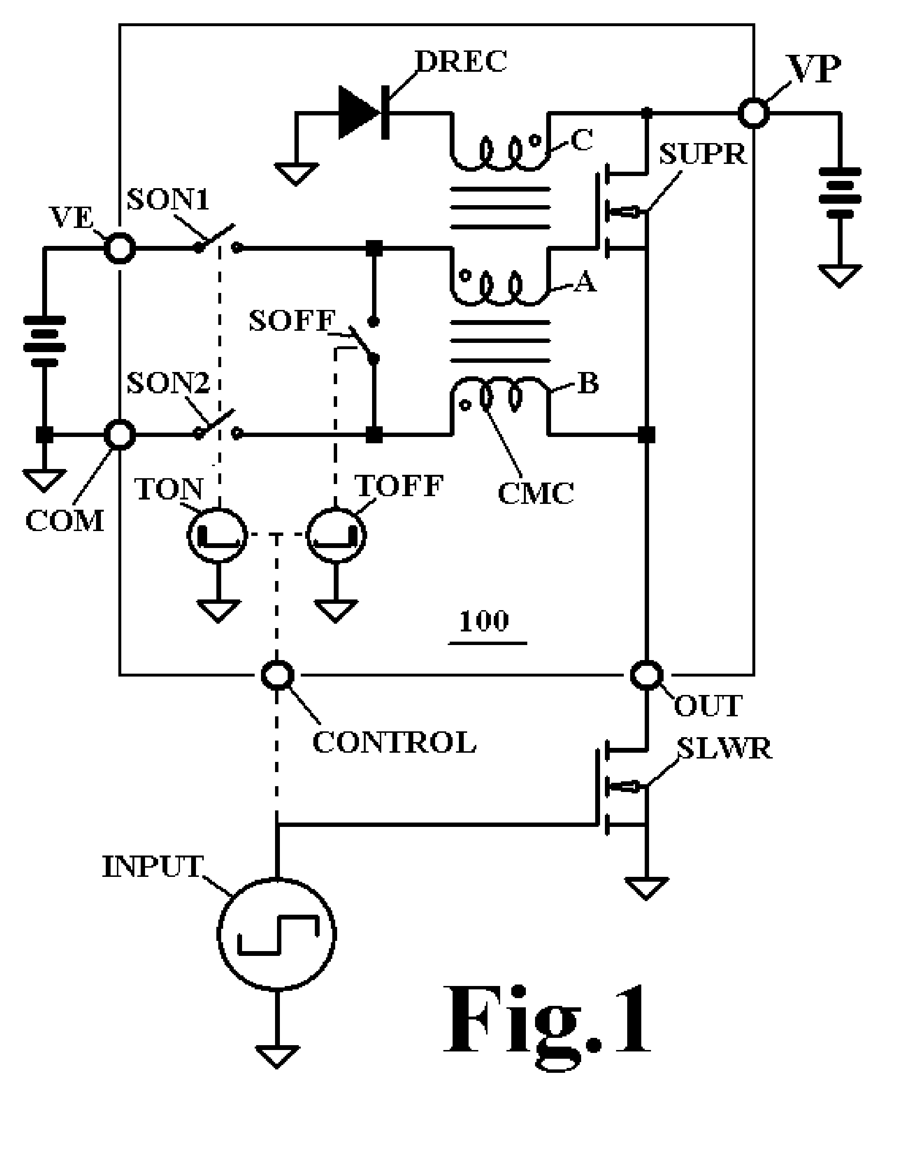
[0012]Referring to first FIG. 1, there is depicted a switch 100 according to the present invention, shown embedded in a typical totem pole circuit according to the prior art. A power voltage source is shown applied through a terminal VP. A switch enhancement voltage source is shown applied through a terminal VE. A control signal is shown applied through a terminal CONTROL. A totem pole output is shown connected through a terminal OUT. A common return is shown connected through a terminal COM. Inside switch 100 is shown a high-side FET switch SUPR. Outside switch 100 is shown low-side FET switch SLWR. Connected through terminal OUT these two FET's form a well-known totem pole circuit. A control signal from a generator INPUT both controls FET SLWR and enters switch 100 through terminal CONTROL. For the polarity switches used in this figure, SLWR is on when the signal at terminal CONTROL is positive, and off when it is negative.

[0013]Inside switch 100, the falling edge of the signal at...


PUM


Abstract

A common-mode choke level-shifter drives a power switch with sub-nanosecond timing integrity without requiring a high-side gate-drive power supply. The same level-shifter may also be used to drive a low-side switch to avoid ground bounce effects.

Description

CROSS-REFERENCE TO RELATED APPLICATIONS[0001]The present application claims the benefit of U.S. Provisional Application No. 61 / 263,527 filed on Nov. 23, 2009, which is incorporated herein by referenceSTATEMENT REGARDING FEDERALLY SPONSORED RESEARCH OR DEVELOPMENT[0002]The present invention was not developed with the use of any Federal Funds, but was developed independently by the inventors.BACKGROUND OF THE INVENTION[0003]Several techniques are used in the prior art to control a power FET or IGBT used in the upper, or high-side, position of a well known “totem-pole” power circuit. If a P-channel device be used at a relatively large positive voltage, or an N-channel device for a negative voltage, a semiconductor level shifter may be used to control a current which can be dropped across a resistor to enhance the switch. This method does not require a high-side enhancement supply, but is relatively slow, limiting its utility to power-converters operating below a few tens of KHz. Someti...

Claims


Application Information

Patent Timeline
IPC IPC(8): H02M3/335
CPCH03K17/04206H02M3/155
Inventor LAWSON, THOMAS E.MORONG, WILLIAM H.
Owner COGNIPOWER
Features
  • Generate Ideas
  • Intellectual Property
  • Life Sciences
  • Materials
  • Tech Scout
  • Unparalleled Data Quality
  • Higher Quality Content
  • 60% Fewer Hallucinations
Learn More