Optical ultrasonic microphone

a technology microphones, applied in the field of optical ultrasonic microphones, can solve the problems of difficult formation of microphones having diaphragms, difficult to form microphones having diaphragms, and the high frequency band limitation of vibration measurements in the ldv to be used easily exceeds 1 mhz, so as to avoid reflection influences, improve the accuracy of sound pressure measurement, and avoid the effect of reflection

Active Publication Date: 2011-05-26
PANASONIC CORP
View PDF12 Cites 13 Cited by
  • Summary
  • Abstract
  • Description
  • Claims
  • Application Information

AI Technical Summary

Benefits of technology

[0055]In accordance with the optical ultrasonic microphone of the present invention, the sound wave that is propagated through a gas in the ambient space is received from the opening to the acoustic waveguide, and by measuring the sound wave that proceeds through the inside of the optical acoustic propagation medium from the inside of the acoustic waveguide by the use of light, it becomes possible to carry out measurements up to a high-frequency region that greatly exceeds the limitation of a conventional diaphragm due to its mechanical resonance and the like, and also to carry out a precise sound pressure measurement with high sensitivity, while avoiding influences of reflection of the sound wave caused by a conventional electric acoustic converter made of a piezoelectric ceramic material and the like.

Problems solved by technology

That is, although it has a comparatively flat frequency characteristic in frequencies lower than the mechanical resonance frequency of the diaphragm, its sensitivity abruptly drops at frequencies above the resonance frequency, with the result that the upper limit as the microphone is limited to the proximity of the resonance frequency.
Therefore, it is very difficult to form a microphone having a diaphragm whose band characteristic is expanded to 100 kHz or more, with its sensitivity being sufficiently maintained.
Furthermore, the high-frequency band limitation of vibration measurements in the LDV to be used easily exceeds 1 MHz.
Therefore, it becomes very difficult to miniaturize the corresponding measuring area.
Therefore, in a high-frequency region, a sound wave interference easily occurs in the measuring area, making it difficult to measure an accurate sound pressure.
That is, since the high frequency band limitation of the microphone is determined by the dimension of the measuring range, and since the sound velocity in air is slower than the elastic wave velocity of a general-use diaphragm, the high frequency band limitation becomes lower in the case of the laser Doppler microphone when the measuring area and the diaphragm have the same area.
In the conventional optical microphone, although the band width for optical measurements is sufficiently wide, since the high-frequency band is limited by the mechanical resonance or the cavity resonance to be utilized, an issue arises in which it becomes difficult to carry out operations in an ultrahigh-frequency area having, in particular, 100 kHz or more.

Method used


Image

  • Optical ultrasonic microphone
  • Optical ultrasonic microphone
  • Optical ultrasonic microphone

Examples


first embodiment

[0114]Referring to FIGS. 1A to 4, a first embodiment of the present invention will be explained.

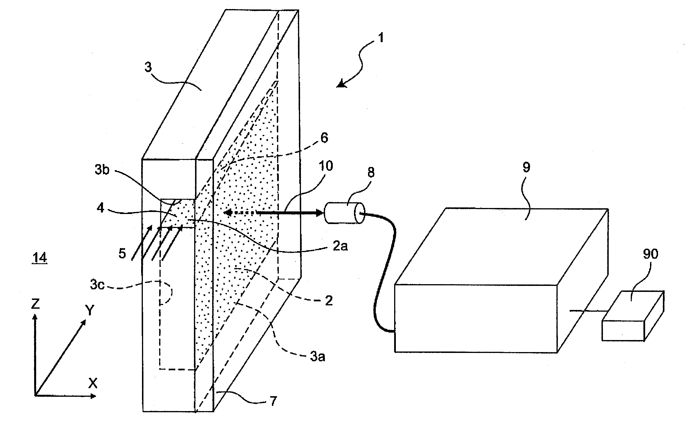
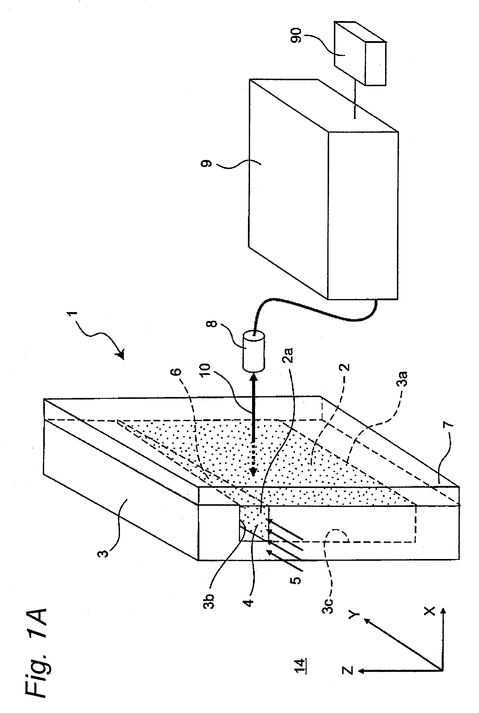
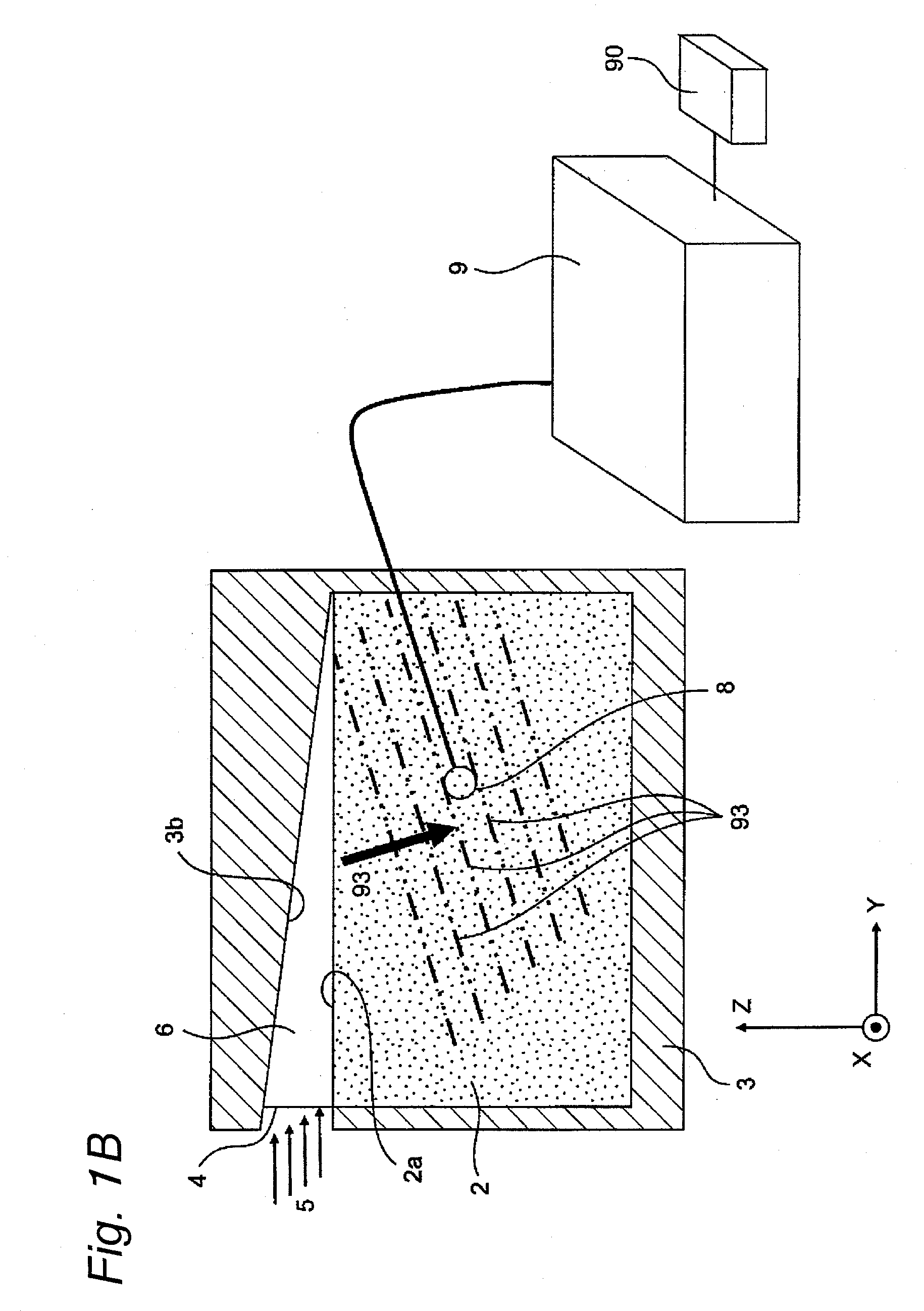
[0115]FIGS. 1A and 1B are a perspective view and a partial cross-sectional front view that show a structure of an optical ultrasonic microphone 1 in accordance with the first embodiment. As shown in FIGS. 1A and 1B, suppose that the height direction is defined as a Z-direction, and that two directions that are mutually orthogonal to the height direction are defined as X and Y-directions so that X, Y, and Z-directions are defined. The optical ultrasonic microphone 1 is disposed in the Y-direction, and the thickness direction of the optical ultrasonic microphone 1 corresponds to the X-direction.

[0116]In FIGS. 1A and 1B, the optical ultrasonic microphone 1, which is a microphone for receiving sound waves (for example, ultrasonic waves) with respect to the peripheral space of the optical ultrasonic microphone 1 filled with a gas 14 (for example, air), is provided with: a base 3 including an o...

second embodiment

[0143]FIG. 5A is a perspective view that shows a structure of an optical ultrasonic microphone 51 in accordance with a second embodiment of the present invention. Hereinafter, those components that have the same functions and shapes as those of the first embodiment are indicated by the same reference numerals.

[0144]In FIG. 5A as well, reference numeral 51 represents an optical ultrasonic microphone, 52 represents an optical acoustic propagation medium portion that has the same functions as the optical acoustic propagation medium portion 2 of the first embodiment, and is constructed by a dried silica gel that is one example of the optical acoustic propagation medium, 53 represents a base that has the same functions as the base 3 of the first embodiment, represents an opening of an acoustic horn (converging unit), 55 represents a sound wave propagation direction of a sound wave (for example, ultrasonic sound wave), 56 represents an acoustic waveguide member used for forming an acousti...

third embodiment

[0213]FIG. 9 is a YZ cross-sectional view that shows an optical ultrasonic microphone 91 in accordance with a third embodiment of the present invention. The structure shown in FIG. 9 differs from that of the first embodiment shown in FIGS. 1A and 1B in that the relative positional relationship between the LDV head 8 and the dried silica gel serving as one example of the optical acoustic propagation medium portion 2 is different and in that a mirror 92 is installed therein. Reference 94 represents a sound wave propagation direction of a sound wave in the dried silica gel 2, and reference numeral 93 represents an isophase wavefront of the sound wave propagation in a simulated manner.

[0214]That is, the LDV head 8 has its optical axis disposed not in the thickness direction of the optical acoustic propagation medium portion 2, but in a direction orthogonal to the thickness direction, in a manner so as to be made face to face with the mirror 92. Preferably, as shown in FIG. 9, the optica...


PUM


Abstract

An optical ultrasonic microphone includes an acoustic waveguide that transmits a sound wave received from an opening, an optical acoustic propagation medium that forms at least one portion of a wall face of the acoustic waveguide and an LDV head, and a sound wave proceeding through the acoustic waveguide is received by the optical acoustic propagation medium so that a change in the refractive index caused by the proceeding sound wave inside the optical acoustic propagation medium is generated with high efficiency, and by detecting this as an optical modulation by the LDV head, the optical ultrasonic microphone is allowed to have a very wide band.

Description

TECHNICAL FIELD[0001]The present invention relates to a microphone that utilizes light, and in particular, relates to an optical ultrasonic microphone that receives an ultrasonic wave propagated through a gas such as air, and converts the received ultrasonic wave into an electric signal by utilizing light.BACKGROUND ART[0002]As devices that collect a sound wave and convert the sound wave to an electric signal, a dynamic microphone or a capacitor microphone has been widely used in the audible band, and a piezoelectric sensor has been widely used in the ultrasonic region. In these devices, by utilizing the fact that a sound wave is derived from minute vibrations of air, the sound wave is made incident on a diaphragm so that minute vibrations generated on the diaphragm by the sound are converted to an electric signal conductively, electrostatically, or piezoelectrically.[0003]On the other hand, an optical system, such as a laser Doppler vibrometer (hereinafter, referred to simply as “L...

Claims


Application Information

Patent Timeline
Patent Type & Authority Applications(United States)
IPC IPC(8): H04B10/12H04R1/34H04R23/00
CPCG01H9/004
Inventor HASHIMOTO, MASAHIKONAGAHARA, HIDETOMOSUGINOUCHI, TAKEHIKO
Owner PANASONIC CORP
Why Eureka
Try Eureka