
Control device for power transmission device for vehicle

a technology of power transmission device and control device, which is applied in the direction of transportation and packaging, transportation, road transportation, etc., can solve the problems of consumption rate, and achieve the effect of reducing the axial dimension of the differential mechanism

Active Publication Date: 2011-06-02
TOYOTA JIDOSHA KK
View PDF7 Cites 62 Cited by
  • Summary
  • Abstract
  • Description
  • Claims
  • Application Information

AI Technical Summary

Benefits of technology

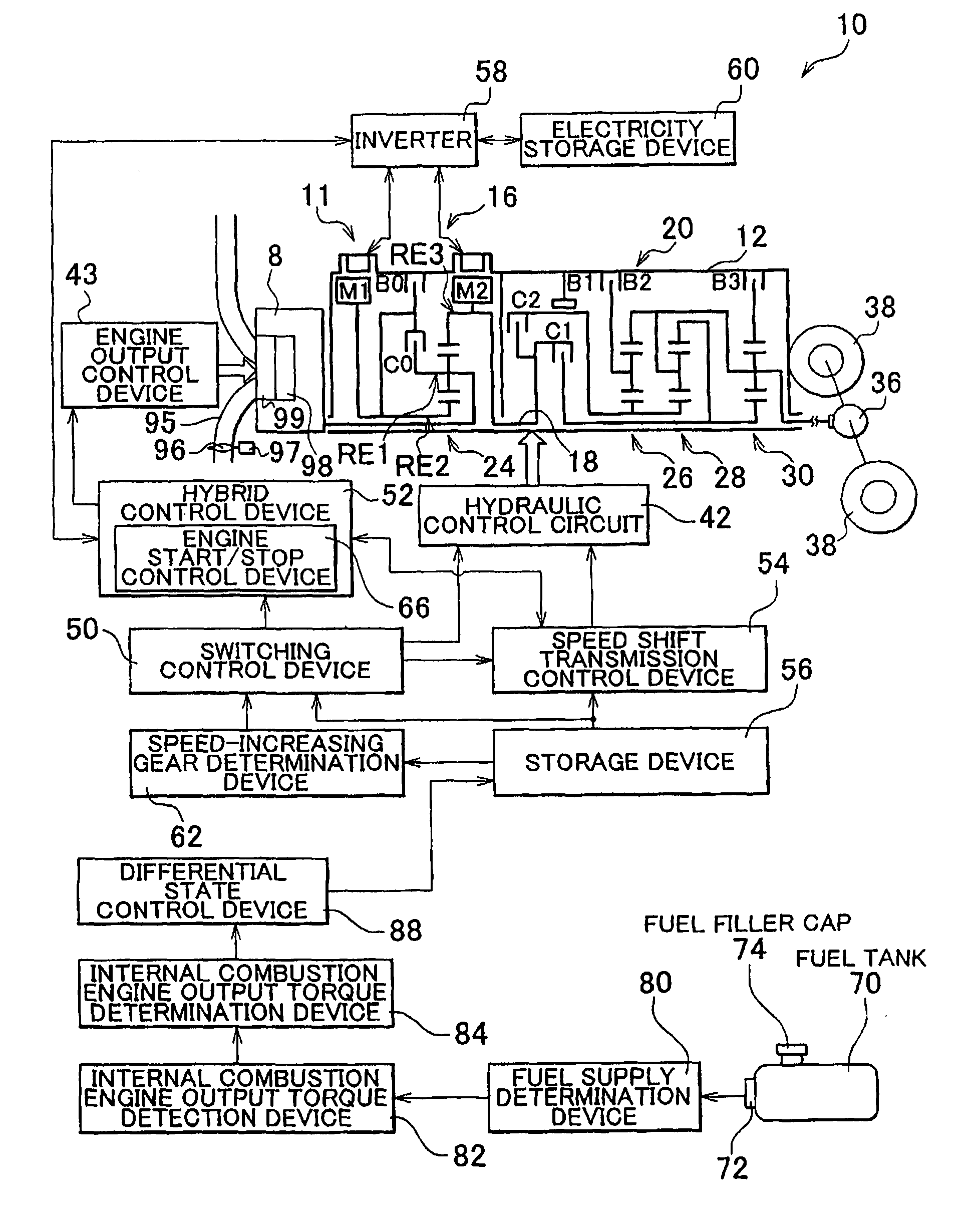
[0006]The present invention has been made in view of the foregoing circumstances, and therefore provides a control device for a power transmission device for a vehicle that can reduce the fuel consumption rate in correspondence with a plurality of types of fuel to be supplied.
[0007]According to an aspect of the present invention, thus, there is provided a control device for a power transmission device for a vehicle that includes an electrical differential part that has a differential mechanism that is coupled between an internal combustion engine and a driving wheel and an electric motor that is coupled to the differential mechanism for power transmission, the electrical differential part controlling a differential state of the differential mechanism by controlling an operating state of the electric motor, and a differential restriction device that is capable of selectively switching the differential mechanism between a non-differential state in which a differential action of the differential mechanism is disabled and a differential enabled state in which the differential action of the differential mechanism is enabled, characterized by further including: a differential state control device that, in the case where the internal combustion engine is driven on a different type of fuel from a reference fuel that is prescribed as a fuel for driving the internal combustion engine and an output torque of the internal combustion engine is thus greater than the output torque of the internal combustion engine produced when the internal combustion engine is driven on the reference fuel, expands a non-differential range, on the basis of which the differential restriction device determines to switch the differential mechanism into the non-differential state, compared to the non-differential range for use when the internal combustion engine is driven on the reference fuel.
[0008]According to the control device for a power transmission device for a vehicle described above, in the case where the internal combustion engine is driven on a different type of fuel from a reference fuel that is prescribed as a fuel for driving the internal combustion engine and an output torque of the internal combustion engine is thus greater than the output torque of the internal combustion engine produced when the internal combustion engine is driven on the reference fuel, the differential state control device that is included in the control device expands a non-differential range, on the basis of which the differential restriction device determines to switch the differential mechanism into the non-differential state, compared to the non-differential range for use when the internal combustion engine is driven on the reference fuel. Thus, in the case where different types of fuel from the reference fuel, that is, a plurality of types of fuel are supplied to the internal combustion engine, the advantage of switching the differential mechanism between the differential enabled state and the non-differential state can be fully utilized in correspondence with the output characteristics of the internal combustion engine, which may vary in accordance with the fuel type. As a result, the fuel consumption rate can be reduced in correspondence with the plurality of types of fuel supplied to the internal combustion engine, for example.

Problems solved by technology

However, the control device according to JP-A-2005-273900 particularly does not modify the predetermined conditions and hence does not reduce the fuel consumption rate in correspondence with a plurality of types of fuel to be supplied.

Method used


Image

  • Control device for power transmission device for vehicle
  • Control device for power transmission device for vehicle
  • Control device for power transmission device for vehicle

Examples


Embodiment Construction

[0038]Hereinafter, an embodiment of the present invention will be described in detail with reference to the drawings.

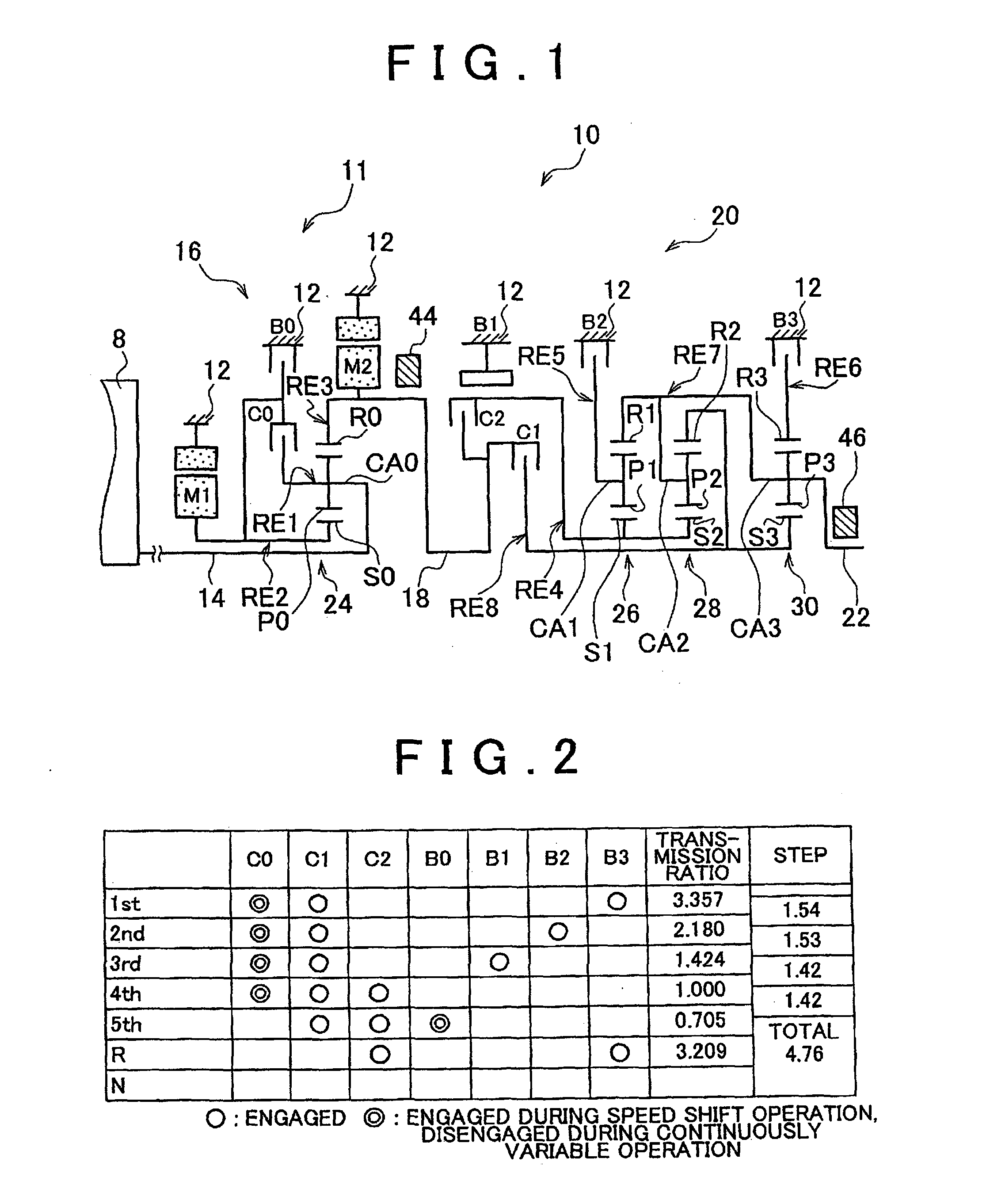
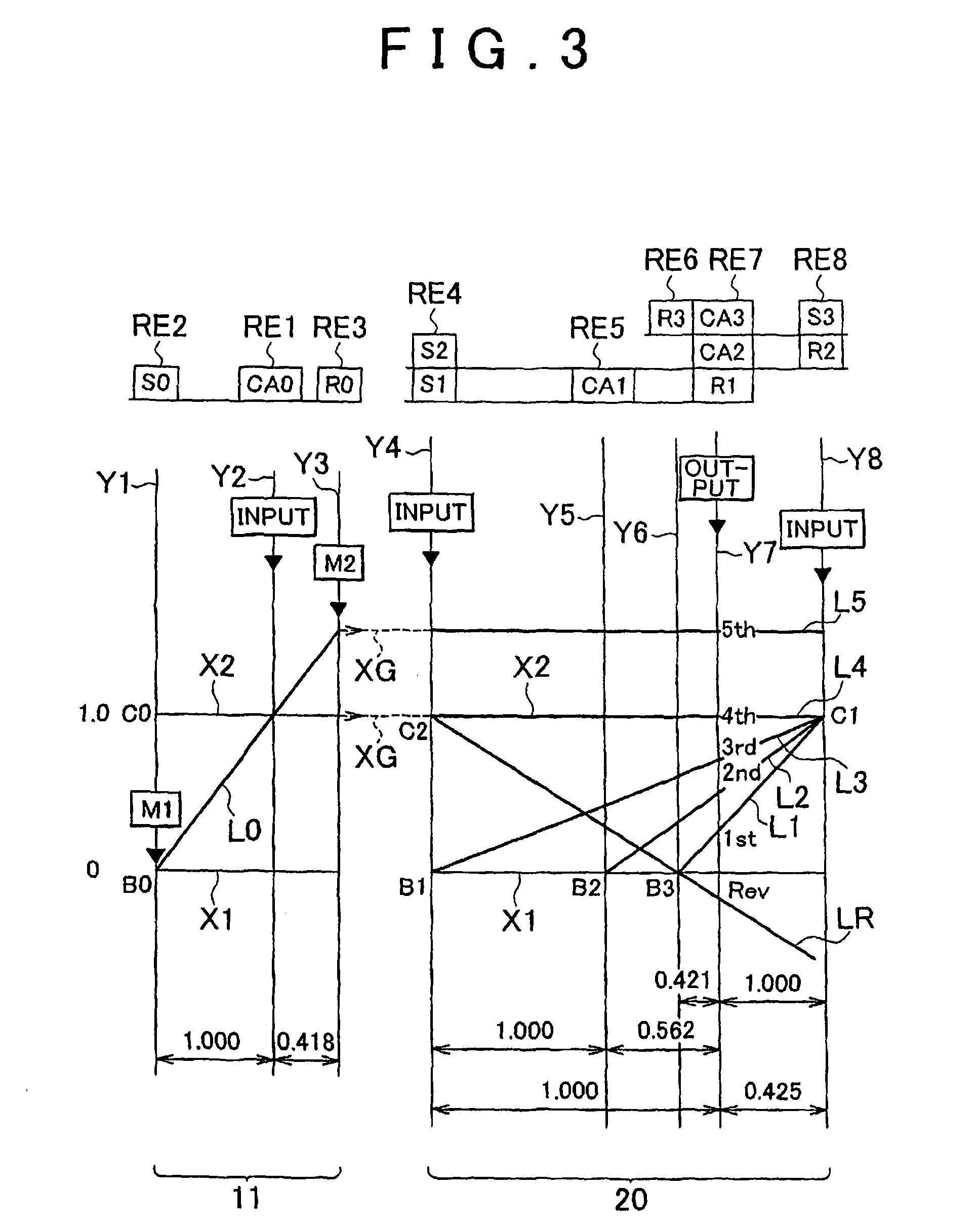
A control device according to the present invention may be used in hybrid vehicles, for example. FIG. 1 is a skeleton diagram that illustrates a power transmission device 10 for a vehicle to which a control device according to the present invention is applied. As shown in FIG. 1, the power transmission device 10 includes an input shaft 14 as an input rotary member disposed on a common axis in a transmission case 12 (hereinafter referred to as “case 12”) as a non-rotary member attached to the vehicle body, a differential part 11 coupled to the input shaft 14 directly or via a pulsation absorption damper (vibration attenuation device) (not shown), an automatic transmission part 20 coupled in series with the differential part 11 via a transmission member (transmission shaft) 18 in a power transmission path between the differential part 11 and driving wheels 38 (see FIG. ...


PUM


Abstract

When an engine is driven on a different type of fuel (for example, ethanol-containing fuel) from a reference fuel (for example, gasoline) and the engine torque is thus greater than that produced when the engine is driven on the reference fuel, a differential state control device expands a non-differential range compared to that at the time when the reference fuel is used. Thus, in the case where a plurality of types of fuel including the reference fuel are supplied to the engine, the advantage of switching a power distribution mechanism between a differential enabled state and a non-differential state can be fully utilized in correspondence with engine torque characteristics which may vary in accordance with the type of fuel for the engine. As a result, the fuel consumption rate can be reduced in correspondence with the plurality of types of fuel supplied to the engine, for example.

Description

BACKGROUND OF THE INVENTION[0001]1. Field of the Invention[0002]The present invention pertains to a control device for a power transmission device for a vehicle, and relates to a technique for using a plurality of types of fuel to drive an internal combustion engine.[0003]2. Description of the Related Art[0004]Conventionally, there has been known a power transmission device for a vehicle including a differential part that has a differential mechanism coupled between an internal combustion engine and driving wheels and a first motor coupled to the differential mechanism and that controls the differential state of the differential mechanism by controlling the operating state of the first motor, a speed shift transmission coupled between the differential part and the driving wheels, a second motor coupled to the input side of the speed shift transmission, and a differential restriction device capable of selectively switching the differential mechanism between a non-differential state i...

Claims


Application Information

Patent Timeline
IPC IPC(8): B60W20/00B60W10/10B60W10/08B60K6/445B60K6/547B60W10/06F16H59/34F16H61/02F16H61/68F16H61/684F16H61/686F16H63/50
CPCB60K6/445B60K6/48B60W10/02B60W10/06B60W10/105Y02T10/76B60W2560/04B60W2560/06F16H2037/0873Y02T10/6221Y02T10/6239B60W20/00B60W2530/211B60W2530/213Y02T10/62B60W20/40
Inventor IMAMURA, TATSUYAMATSUBARA, TOORUTABATA, ATSUSHIIWASE, YUJIKUMAZAKI, KENTAIMAI, KEITA
Owner TOYOTA JIDOSHA KK
Learn More