Dip guided full waveform inversion

a full waveform and inversion technology, applied in the field of dipguided full waveform inversion, can solve the problems of large amount of processing, difficult to apply this technique, and large size of inversion, so as to reduce the size of inversion and computational cost, mitigate some of the shortcoming of fwi, and reduce the difficulty of applying this technique.

Inactive Publication Date: 2011-06-02
CONOCOPHILLIPS CO
View PDF27 Cites 69 Cited by
  • Summary
  • Abstract
  • Description
  • Claims
  • Application Information

AI Technical Summary

Benefits of technology

[0009]In order to overcome the difficulties of FWI, a method using dip-guide methodology with the full waveform inversion process, or “dip-guided full waveform inversion” (DG-FWI) is utilized to generate velocity models. The process is two-fold, using Hale's (Hale, 2009) image-guided interpolation methodology and a revised FWI methodology with a DG-FWI approach which incorporates dimension reduction techniques (e.g. Yang & Meng, 1996) that can greatly reduce the difficulties encountered in FWI, both incorporated by reference. The DG-FWI reduces the size of the inversion and the computational cost while it mitigates some of FWI's shortcoming with respect to the dependence on the very low-frequency seismic data; and generally improves model convergence.

Problems solved by technology

However, despite the significant potential, it has been challenging to apply this technique, which may be formulated in either time (Lailly, 1983; Tarantola, 2005) or frequency domains (Pratt, 1999 a & b), on full-scale 3D models.
Full wave form inversions (FWI) are difficult to perform, simulating large quantities of data, and require a large amount of processing to achieve a final model that incorporates lithology in the seismic data.
Because many of these methods sample the data in a uniform and unweighted manner, changes in the data and the underlying lithology may be overlooked by these models.
This is complicated by noise in the seismic data and artifacts within the data that obscure the true lithology.

Method used


Image

  • Dip guided full waveform inversion
  • Dip guided full waveform inversion
  • Dip guided full waveform inversion

Examples


example 1

Synthetic Data Analysis

[0032]To test the DG-FWI, model data were generated. A true model was generated by referencing V(z) to a water bottom, adding a deep flat reflector, low velocity gas zone (LVZ) and a high velocity bar (HVB) anomalies. By definition, the starting model was the true model without two anomalies. The true dataset was “generated” with 148 shots with a spacing of 60 ft. Receiver spacing was at 30 ft with a depth interval of 30 ft. The dominant frequency in this model was 10 Hz, quite high for FWI but is intentionally designed to test the robustness of the DG-FWI. This true model was used to generate synthetic data that represent the features and anomalies as described.

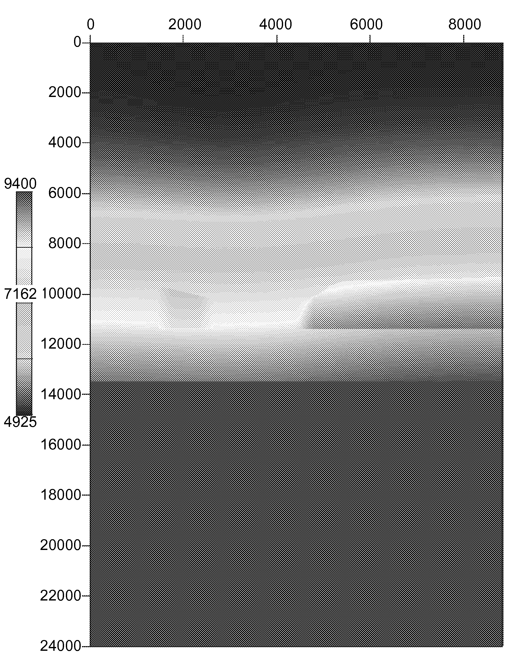
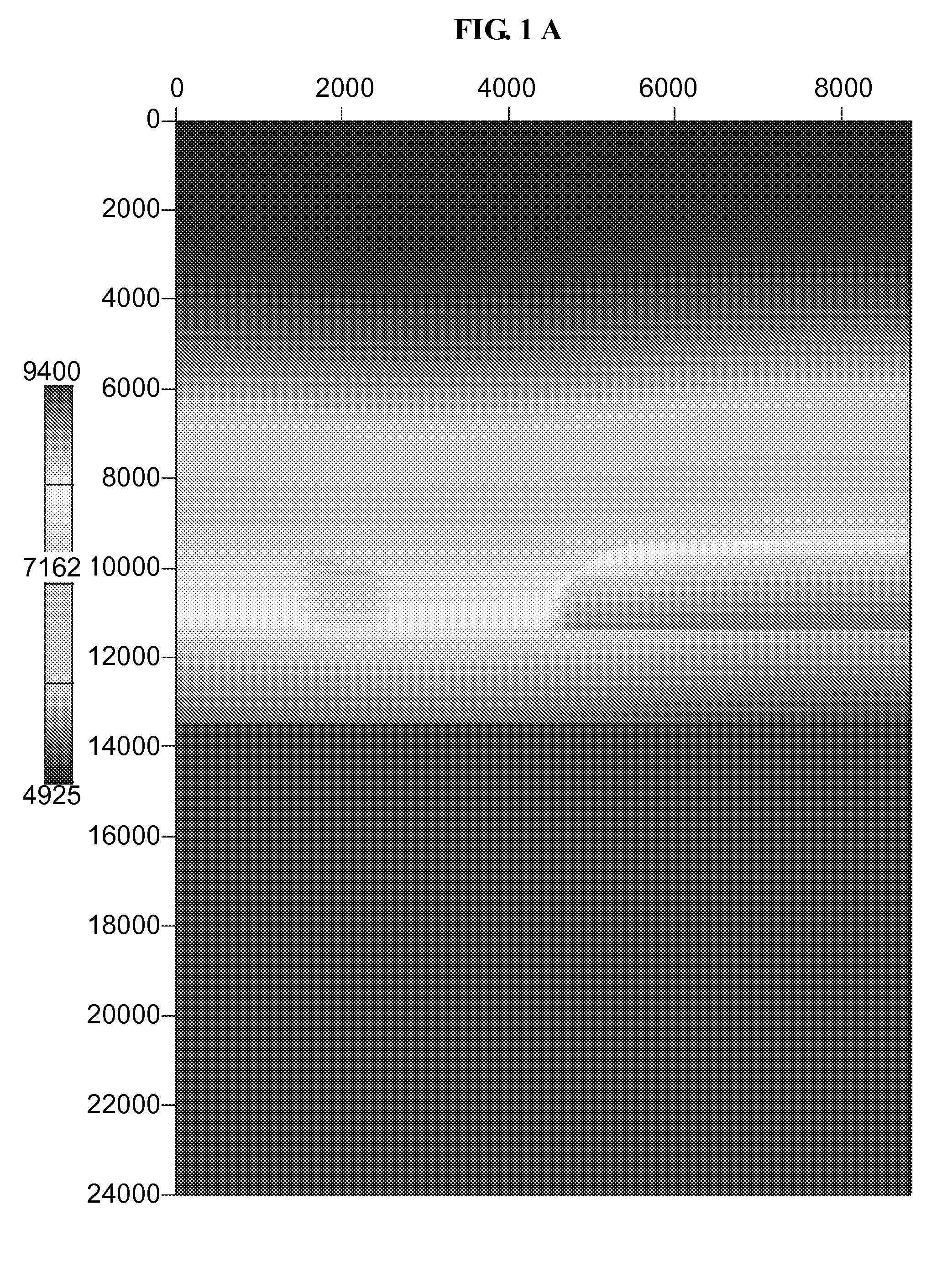
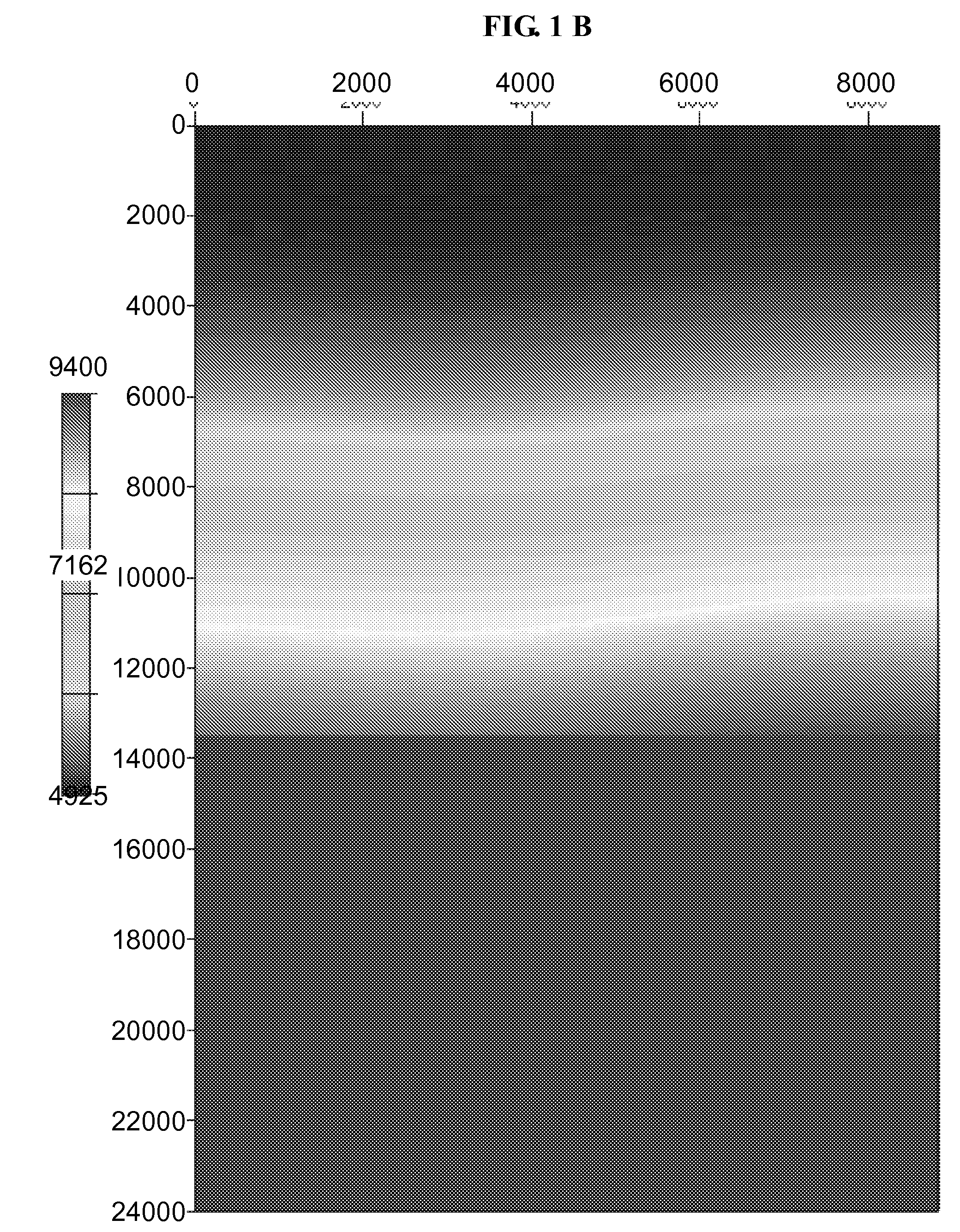
[0033]FIG. 1. shows the true model, the starting model and their difference. The true velocity model FIG. 1A shows features including the water bottom, a low velocity zone (LVZ), a high velocity bar (HVB), and a deeper flat reflector. This simple model was analyzed with an initial velocity model FIG. 1...

example 2

Anaylisis within a Low Velocity Gas Zone

[0039]Although DG-FWI accurately assessed the structures and anomalies within a synthetic dataset a more complex system was analyzed to determine applicability to field data. As shown in FIG. 7A, an initial model was used for this test. For this data, each FWI required approximately 2 hours on a 100-node cluster. This data, made up of ˜1200 shots with a 25 m spacing, was acquired to image a gas cloud anomaly. The receivers were spaced at 12.5 m and a depth of 10 m. Anomalies and features for this dataset were not pre-defined and the model was developed based solely on the DG-FWI analyses. An RTM image with the starting model is overlain with the dip guide tensors that will guide the DG-FWI analyses. Although the samples are regularly selected (20×10), the dip guide provides accurate and relevant guidance for the subsequent FWI inversion, and the underlying data dictate the size, shape and direction of the tensor.

[0040]The updated DG-FWI veloci...


PUM


Abstract

A method of determining seismic data velocity models comprising dip-guided full waveform inversion that obtains a better velocity model with less computational requirements. DG-FWI quickly converges to provide a better image, obtains better amplitudes, and relies less on lower frequencies. Improved image quality allows detailed seismic analyses, accurate identification of lithological features, and imaging near artifacts and other anomalies.

Description

CROSS-REFERENCE TO RELATED APPLICATIONS[0001]This application is a non-provisional application which claims benefit under 35 USC §119(e) to U.S. Provisional Application Ser. No. 61 / 240,794 filed Sep. 9, 2009, entitled “DIP GUIDED FULL WAVEFORM INVERSION,” which is incorporated herein in its entirety.STATEMENT REGARDING FEDERALLY SPONSORED RESEARCH[0002]None.FIELD OF THE DISCLOSURE[0003]The present disclosure generally relates to dip-guided full waveform inversion (DG-FWI) that combines dip-guide methodology (Hale, 2009) with the full waveform inversion (FWI) process (e.g. Bunks, et al., 1995; Pratt, 1999) to obtain a dimension reduction technique (e.g. Yang & Meng, 1996) that can greatly reduce difficulties encountered in FWI.BACKGROUND OF THE DISCLOSURE[0004]Full waveform inversion (FWI), is a well studied and extensively published subject (e.g. Bunks, et al., 1995; Pratt, 1999). Recent technical developments have shown that seismic velocities produced by FWI can produce high resol...

Claims


Application Information

Patent Timeline
Patent Type & Authority Applications(United States)
IPC IPC(8): G06F17/10
CPCG01V1/303
Inventor MENG, ZHAOBO
Owner CONOCOPHILLIPS CO
Why Eureka
Try Eureka