
Systems and methods for assembling a bore repair assembly for use in a wind turbine

a technology for wind turbines and parts, applied in the direction of machines/engines, manufacturing tools, and large components, can solve the problems of significant fatigue cycles on the gearbox assembly and/or other components of the wind turbine, bearings which support the high speed shaft may become worn, and the large components are often subjected to increased loads

Inactive Publication Date: 2011-06-09
GENERAL ELECTRIC CO
View PDF9 Cites 9 Cited by
  • Summary
  • Abstract
  • Description
  • Claims
  • Application Information

AI Technical Summary

Benefits of technology

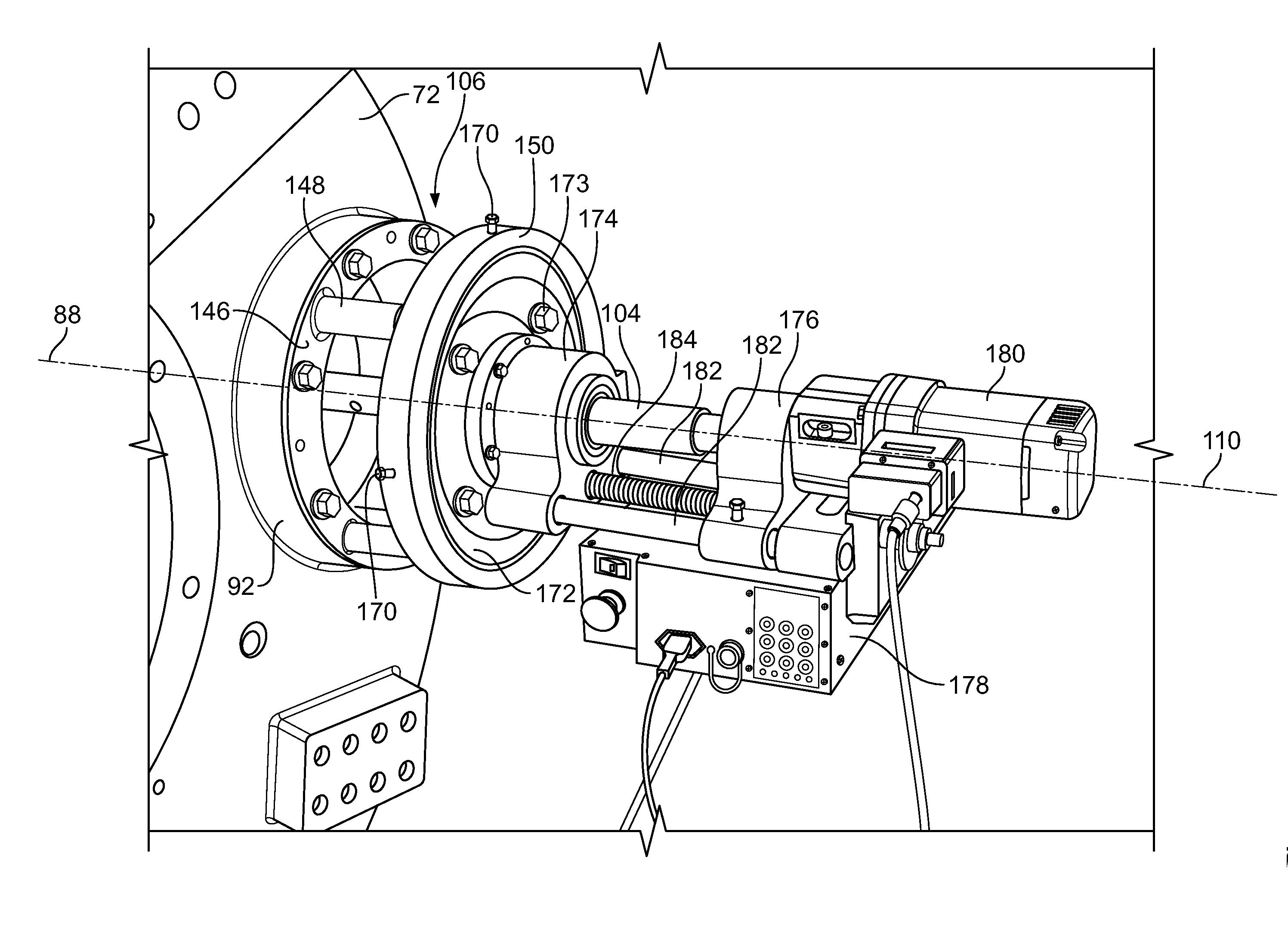
[0009]The embodiments described herein facilitate repairing a gearbox assembly without requiring the nacelle to be removed from the wind turbine. More specifically, the bore repair assembly described herein facilitates repairing a high speed bearing bore to include predetermined dimensions without removing the nacelle, generator, and / or gearbox from the wind turbine.

Problems solved by technology

However, the larger components are often subjected to increased loads (e.g., asymmetric loads) that result from wind shears, yaw misalignment, and / or turbulence, and the increased loads have been known to contribute to significant fatigue cycles on the gearbox assembly and / or other components of the wind turbine.
Over time, the bearings which support the high speed shaft may become worn.
As the bearings become worn, the gearbox assembly becomes less effective in transferring rotational energy to the generator.
In some cases, the bearings can fail which results in damage to the bearing bores.
In some wind turbines, the blades are between 60 and 100 meters in length, and as such, repairing worn or damaged bearing bores can be costly and time-consuming.

Method used


Image

  • Systems and methods for assembling a bore repair assembly for use in a wind turbine
  • Systems and methods for assembling a bore repair assembly for use in a wind turbine
  • Systems and methods for assembling a bore repair assembly for use in a wind turbine

Examples


Embodiment Construction

[0018]The embodiments described herein include a wind turbine system that enables the maintenance of the gearbox assembly without requiring the nacelle, generator, and / or gearbox assembly of the wind turbine to be removed. More specifically, the bore repair assembly described herein enables the high speed bearing bore and / or output shaft to be repaired uptower.

[0019]As used herein, the term “wind turbine” is intended to be representative of any device that generates rotational energy from wind energy, and more specifically, converts kinetic energy of wind into mechanical energy. As used herein, the term “wind generator” is intended to be representative of any wind turbine that generates electrical power from rotational energy generated from wind energy, and more specifically, converts mechanical energy converted from kinetic energy of wind to electrical power. As used herein, the term “uptower” is intended to be representative of any location of the wind turbine that is above a supp...


PUM

PropertyMeasurementUnit
Diameteraaaaaaaaaa

Abstract

A method of assembling a bore repair assembly for use with a wind turbine. The wind turbine includes a gearbox assembly that defines a first bearing bore and a second bearing bore coaxially aligned with the first bearing bore. The method includes coupling a first support assembly with respect to the second bearing bore. A boring bar is positioned coaxially within the first bearing bore and through the second bearing bore. The boring bar is rotatably coupled to the first support assembly. A boring bar drive assembly is coupled to the boring bar for rotating the boring bar about a central bearing axis.

Description

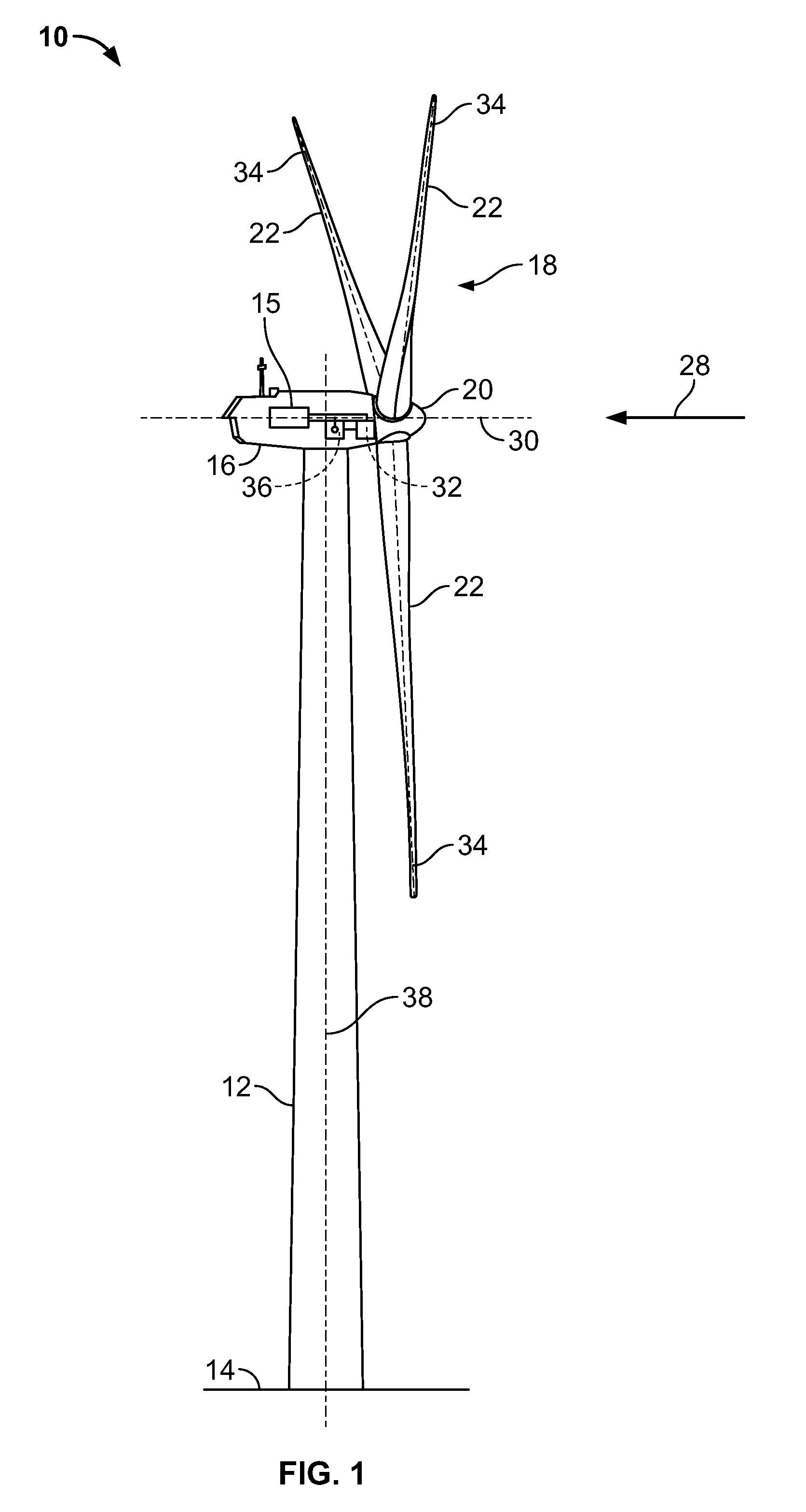
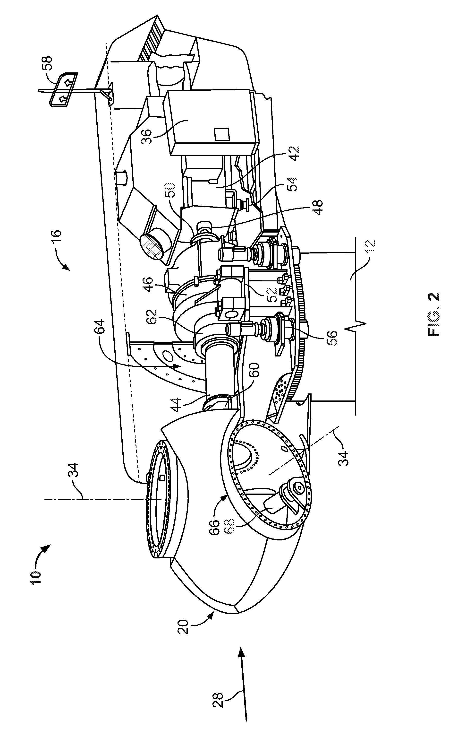
BACKGROUND OF THE INVENTION[0001]The subject matter described herein relates generally to methods and systems for assembling a bore repair assembly for use in a wind turbine.[0002]At least some known wind turbine towers include a nacelle fixed atop a tower. The nacelle includes a rotor assembly coupled to a generator through a shaft. In known rotor assemblies, a plurality of blades extend from a rotor. The blades are oriented such that wind passing over the blades turns the rotor and rotates the shaft, thereby driving the generator to generate electricity.[0003]Because many known wind turbines provide electrical power to utility grids, at least some wind turbines have larger components (e.g., rotors in excess of thirty-meters in diameter) that facilitate supplying greater quantities of electrical power. However, the larger components are often subjected to increased loads (e.g., asymmetric loads) that result from wind shears, yaw misalignment, and / or turbulence, and the increased lo...

Claims


Application Information

Patent Timeline
IPC IPC(8): B23P6/00B23P11/00B23B41/12
CPCB23B29/02B23B41/12F03D1/003F03D11/0008Y10T29/53961Y02E10/722Y10T29/49826Y10T408/89F16H1/28F03D80/70F03D80/50Y02E10/72
Inventor SMITH, ALISTAIR JEFFREYJONES, DOUGLAS JEROMEPLUMMER, JEREMY CLAYTONMADGE, JAMES HENRYMARSDEN, KEITH ALANDEMO, WAYNE ALAN
Owner GENERAL ELECTRIC CO
Learn More