
Soot Pressing for Optical Fiber Overcladding

a technology of optical fiber and cladding, applied in the field of soot pressing for optical fiber overcladding, can solve the problems of inability to meet the requirements of the application, so as to reduce the diameter of the rolled sheet

Inactive Publication Date: 2011-06-09
CORNING INC
View PDF22 Cites 37 Cited by
  • Summary
  • Abstract
  • Description
  • Claims
  • Application Information

AI Technical Summary

Benefits of technology

In other embodiments the pressure is applied axially. For example, silica glass soot may be pressurized in an axial direction to form a soot compact having a density of at least 0.5 g/cc around the glass core, more preferably at least 0.65 g/cc, and even more preferably to at least 0.75 g/cc (e.g., 0.75 g/cc to 1.2 g/cc or 0.8 g/cc to 1.1 g/cc).
In other embodiments the pressure is applied both axially and radially inwards, which may or may not be done simultaneously. For example, the pressure may be 25 psig to 250 psig against the particulate glass material to pressurize the particulate glass material density of at least 0.5 g/cc, preferably at least 0.65 g/cc, and more preferably to at least 0.75 g/cc (e.g., 0.75 g/cc to 1.2 g/cc or 0

Problems solved by technology

Conventional chemical vapor deposition (CVD) processes, such as outside vapor deposition (OVD) and vapor axial deposition (VAD) processes, for making optical fiber preforms often utilize only a portion of the starting raw material due to limitations in the deposition efficiency of the OVD process.
Use of the resulting “waste” silica soot could, therefore, potentially result in significant raw material cost savings.
These methods can suffer from a variety of drawbacks including expensive, complicated, and / or time consuming processing conditions and equipment, and may result in preforms with less than desirable properties such as unacceptable variability with respect to preform density and geometry.
However, the formation of the cladding layer is often the rate limiting step in maximizing optical fiber output.
However, in order to obtain good optical performance, the dimensions of the drilled holes must be very precise and require a significant amount of post-processing, resulting in an increase in the processing cost of these fibers.

Method used


Image

  • Soot Pressing for Optical Fiber Overcladding
  • Soot Pressing for Optical Fiber Overcladding
  • Soot Pressing for Optical Fiber Overcladding

Examples


example 1

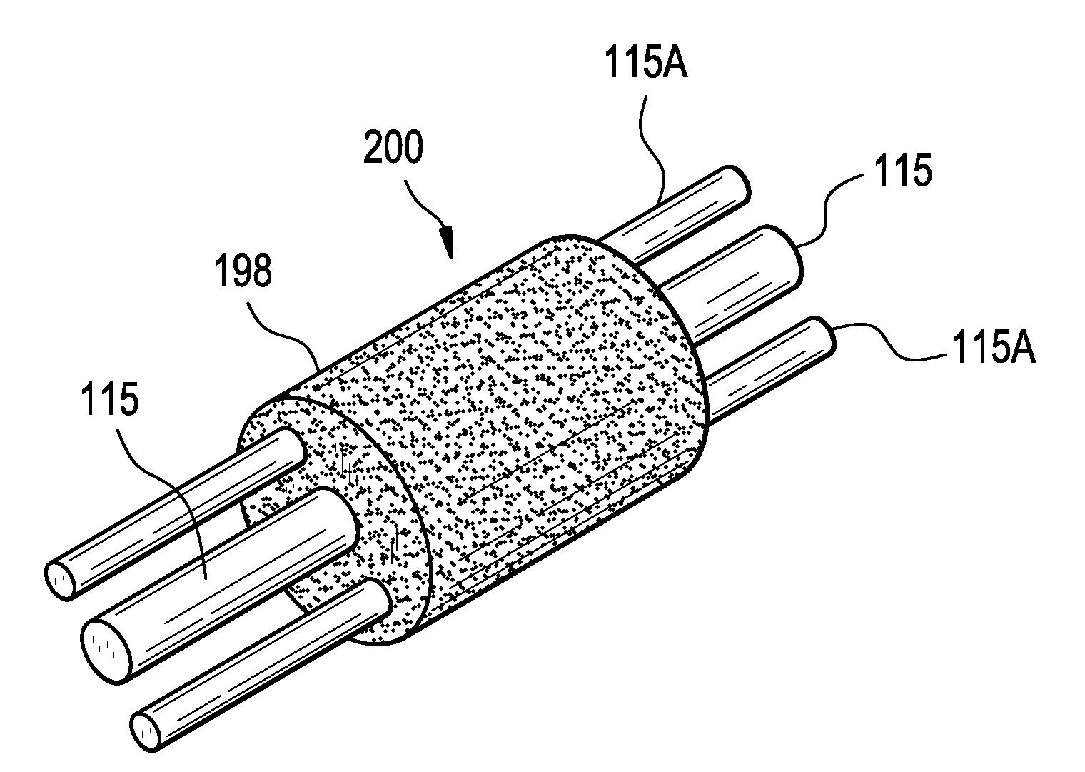
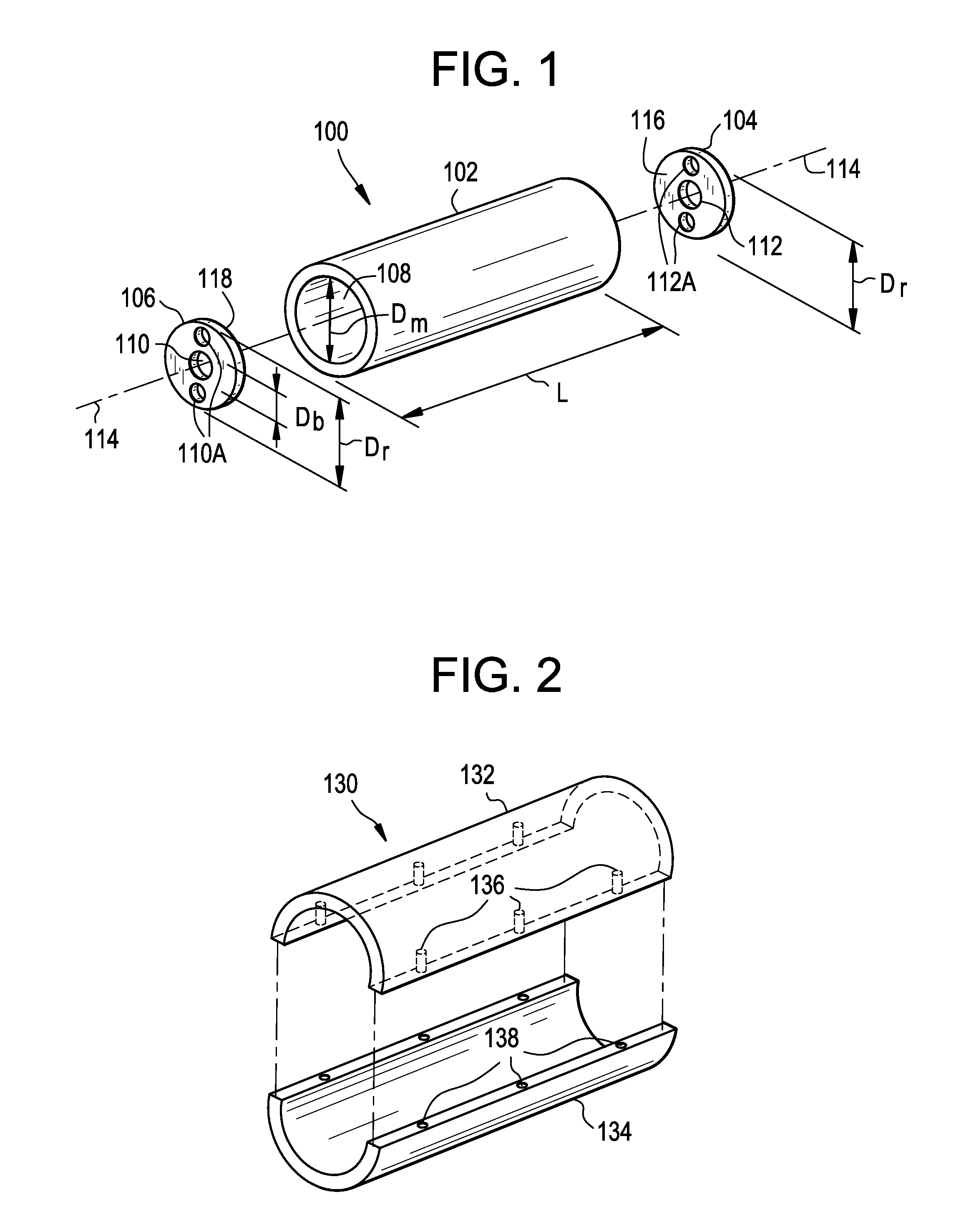
In this example, two optical fiber preform assemblies are prepared by loading the mold cavity with silica glass soot in a single step. To form the optical fiber preform assembly, a glass core cane 1.9 cm in diameter and two stress rods of 24 mm in diameter are positioned in a carbon mold having a mold cavity 89 mm in diameter and a length of 610 mm. The mold cavity is lined with a vitreous carbon coating. The length of the glass core cane in this example is the same as the length of the mold.

The glass core cane is positioned in the mold cavity by inserting an end of the glass core cane in the bore of a ram positioned in the lower portion of the mold cavity. The stress rods are also positioned in the mold cavity by inserting an end of each stress rod in the (off-axis) bore of a ram positioned in the lower portion of the mold cavity. About 930 g of silica glass soot is added to the mold cavity such that the glass core cane is centered in the silica glass soot and the stress rods are p...

example 2

In this example, an optical fiber preform assembly is prepared by loading silica glass soot in the mold cavity in discrete portions and pressing each portion before adding a subsequent portion. To form the optical fiber preform assembly, a glass core cane 19 mm in diameter, and two stress rods of about 24 mm in diameter are positioned in a segmented aluminum mold having a mold cavity 89 mm in diameter and a length of 610 mm. The segmented mold consists of three panels each comprising ⅓rd of the circumference of the mold, and are held together by bolts machined into the outer perimeter of the mold material. The mold cavity is lined with a tight fitting Teflon sheet of thickness of 0.5 mm. The length of the glass core cane and stress rods in this example is the same as the length of the mold. The glass core cane and mold rods are positioned in the mold cavity by inserting an end of the glass core cane and the ends of the mold rods in the bore of a ram positioned in the lower portion o...

example 3

To manufacture an optical preform for making optical fiber, such as the single polarization and / or polarization maintaining fiber with a geometry similar to that shown in FIG. 8C, the positions of the three glass rods (a core rod and two stress rods) in mold assembly are calculated first. In this example, in order to produce a fiber preform, we start with soot that has tap density of 0.6 g / cc. Prior experiments demonstrated that a compacted preform with soot density of 0.85 g / cc. consolidates with axial shrinkage of 19% and radial shrinkage of 29%. An elliptical mold cavity and ram design can compensate for the non-circularly symmetrical position of the glass rods (i.e., for rods being located along one axis of the ellipse, and not along the other axis). In the resultant sintered preform, along the axis containing the core cane and two stress rods, only 35% of the radial profile is glass that originates from compressed soot, while in the orthogonal diameter, 89% of the glass origina...


PUM

PropertyMeasurementUnit
Temperatureaaaaaaaaaa
Fractionaaaaaaaaaa
Fractionaaaaaaaaaa

Abstract

A method and an apparatus for making an optical fiber preform comprising the steps of (i) depositing a plurality of rods are deposited into an inner cavity of an apparatus; (ii) depositing particulate glass material in the inner cavity between the rods and the inner wall; and (iii) applying pressure against the particulate glass material to pressurize the particulate glass material against the plurality of rods.

Description

BACKGROUND OF THE INVENTION1. Field of the InventionThe present invention relates generally to methods and apparatus for making optical fibers with plurality of holes or stress rods that utilize soot pressing for optical fiber overcladding, and particularly to methods and apparatus for making optical fiber preforms.2. Technical BackgroundConventional chemical vapor deposition (CVD) processes, such as outside vapor deposition (OVD) and vapor axial deposition (VAD) processes, for making optical fiber preforms often utilize only a portion of the starting raw material due to limitations in the deposition efficiency of the OVD process. Use of the resulting “waste” silica soot could, therefore, potentially result in significant raw material cost savings.Accordingly, different methods have been devised to utilize otherwise unutilized silica soot in the production of optical fiber preforms. These methods can suffer from a variety of drawbacks including expensive, complicated, and / or time co...

Claims


Application Information

Patent Timeline
IPC IPC(8): C03B37/012
CPCC03B37/01282C03B2203/04C03B2203/42C03B2203/31C03B2203/34C03B2203/14Y02P40/57B29D11/00B29D11/0074C03B19/14C03B37/012C03B37/014G02B6/02
Inventor DAWES, STEVEN BRUCEFILIPPOV, ANDREY V.LI, MING-JUNJENNINGS, DOUGLAS H.KOZLOV, VALERY A.TANDON, PUSHKARWANG, JI
Owner CORNING INC
Features
  • Generate Ideas
  • Intellectual Property
  • Life Sciences
  • Materials
  • Tech Scout
  • Unparalleled Data Quality
  • Higher Quality Content
  • 60% Fewer Hallucinations
Learn More