Laminated inductor, method for manufacturing the laminated inductor, and laminated choke coil

a technology of inductor and choke coil, which is applied in the direction of inductance, inductance with magnetic core, and inductance/yokes, etc., can solve the problems of poor temperature characteristics of the product, and does not allow a sufficient inter-diffusion interface to form, so as to suppress the occurrence of delamination, improve the temperature characteristics of the product, and achieve stable production.

Active Publication Date: 2011-06-09
TAIYO YUDEN KK
View PDF3 Cites 74 Cited by
  • Summary
  • Abstract
  • Description
  • Claims
  • Application Information

AI Technical Summary

Benefits of technology

[0027]The present invention provides a laminated inductor that offers favorable DC superimposition characteristics, is free from variation in temperature characteristics, suppresses occurrence of delamination, and can be produced in a stable manner, as well as a laminated choke coil.
[0028]The aforementioned object and other objects, structural characteristics, and operations and effects of the present invention are made clear by the following explanation and attached drawings.

Problems solved by technology

This has been a problem because the apparent nonmagnetic layer thickness changes with the temperature, resulting in poor temperature characteristics of the product.
However, this specification does not allow a sufficient inter-diffusion interface to form and sometimes separation occurs at the interfacial layer.Patent Literature 1 Japanese Patent Laid-open No.

Method used


Image

  • Laminated inductor, method for manufacturing  the laminated inductor, and laminated choke coil
  • Laminated inductor, method for manufacturing  the laminated inductor, and laminated choke coil
  • Laminated inductor, method for manufacturing  the laminated inductor, and laminated choke coil

Examples


example

[0064]The present invention is explained in greater detail below using an example.

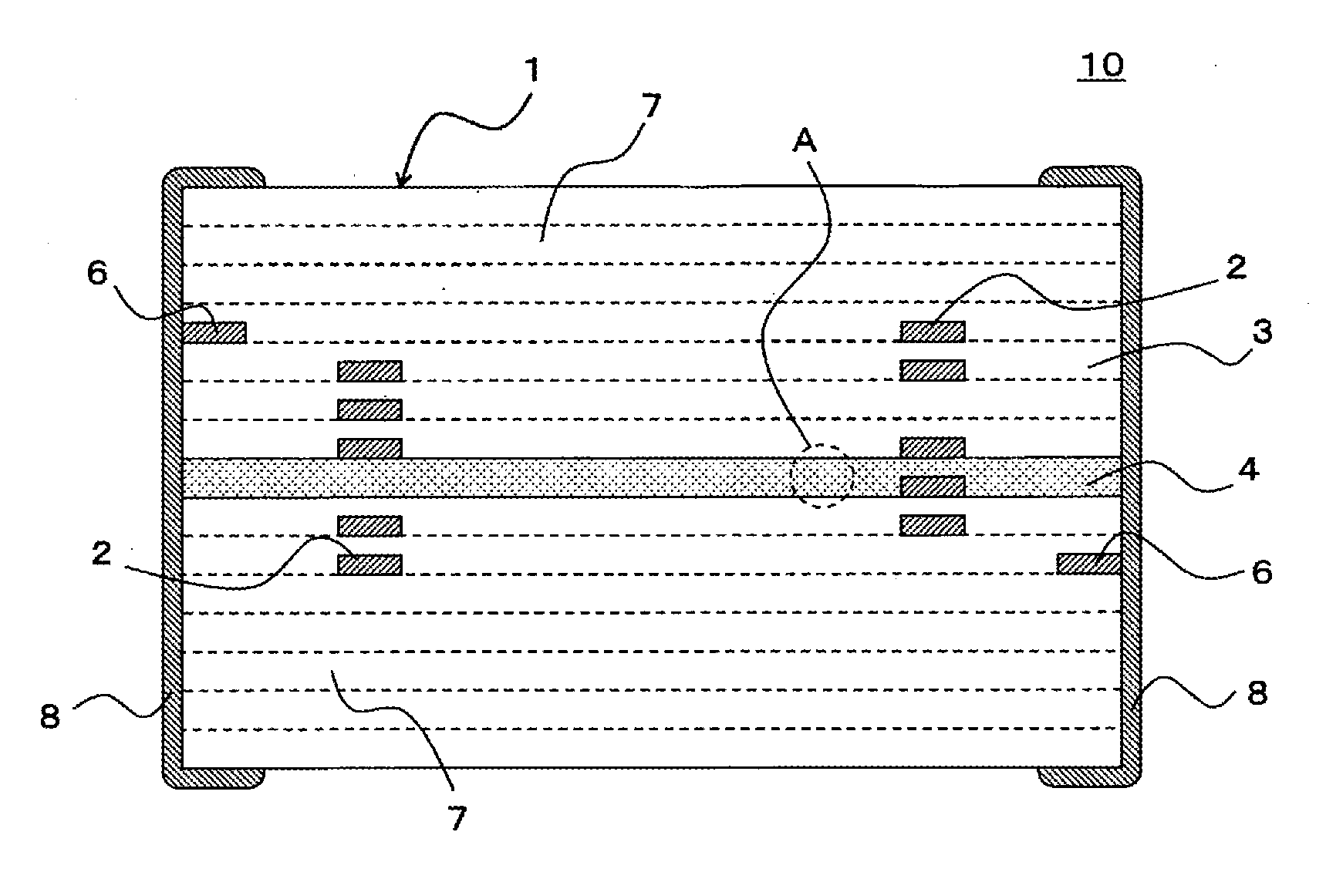
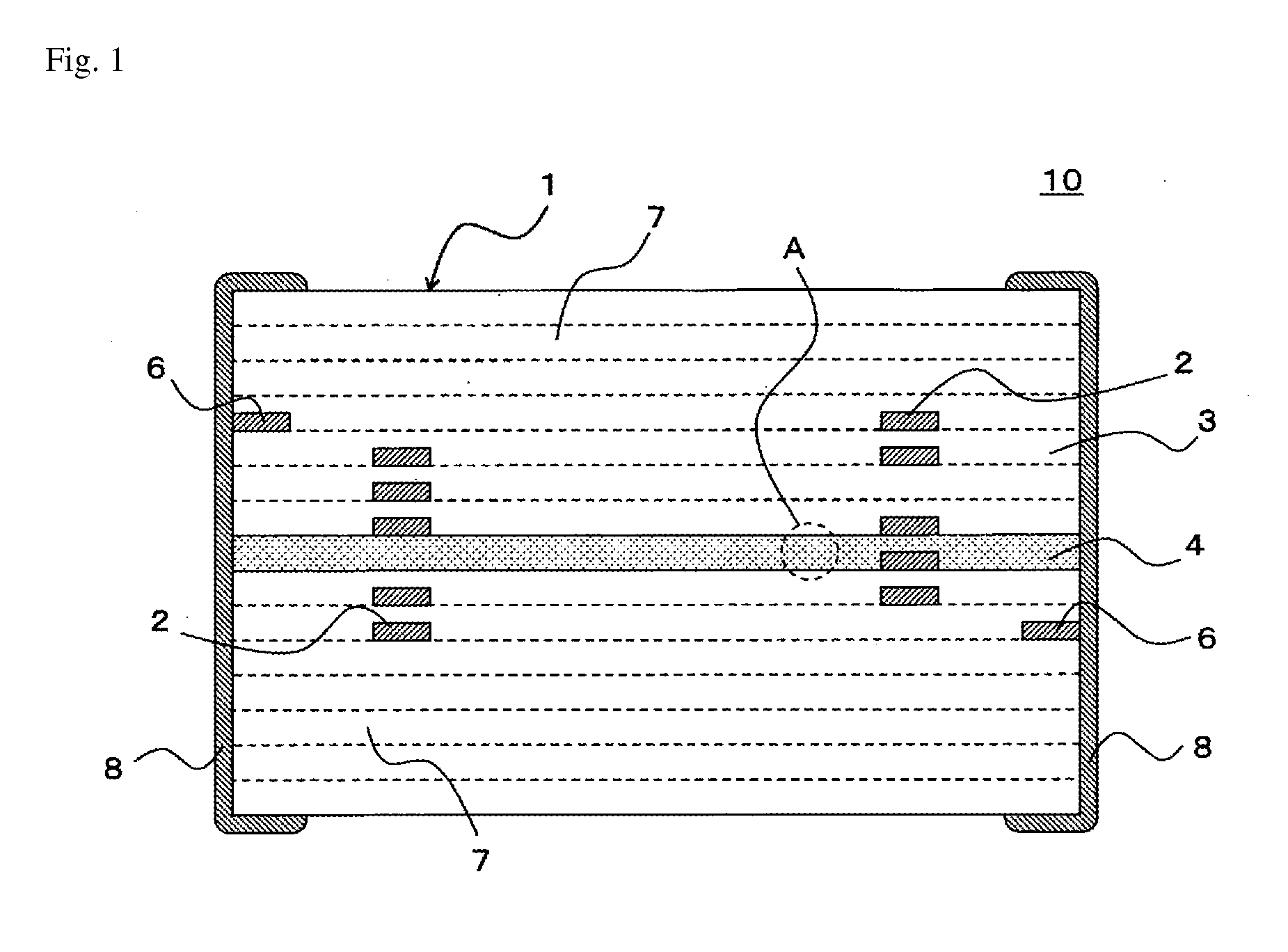
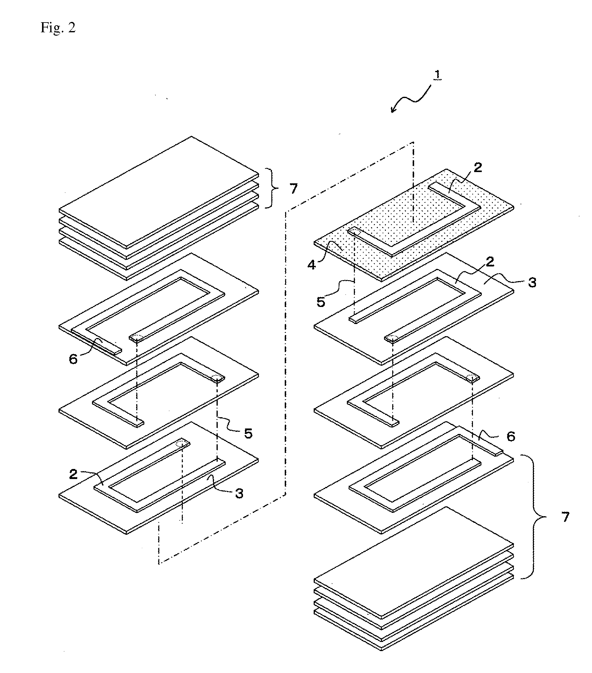
[0065]Ethanol (solvent) and PVA binder were added to and mixed with Ni—Zn—Cu ferrite powder of the composition shown in Table 1 to prepare ferrite powder paste, and this paste was applied on a PET film to obtain a magnetic sheet (magnetic material layer) 3. Solvent and binder were also added to and mixed with powder of a dielectric (low-temperature sintered TiO2 material to which Ag has been added) whose main component is TiO2 and which also contains NiO, CuO, Mn3O4, ZrO2 and Ag2O, as shown in Table 1, to prepare dielectric powder paste in the same manner, and this paste was applied on a PET film to obtain a nonmagnetic sheet (nonmagnetic layer) 4.

[0066]On each green sheet obtained, conductive paste pattern (a C-shaped conductive layer constituting a coil) 2 was printed and then the sheets were laminated to produce a laminate, after which the obtained laminate was cut to unit dimensions to obtain a chi...


PUM

PropertyMeasurementUnit
thicknessaaaaaaaaaa
inter-diffusion distanceaaaaaaaaaa
conductiveaaaaaaaaaa

Abstract

Disclosed is a laminated inductor that has good direct current superimposition characteristics, does not cause a variation in temperature characteristics, suppresses the occurrence of delamination, and can be stably manufactured. Also disclosed are a method for manufacturing the laminated inductor and a laminated choke coil. A laminated inductor (10) for use as a choke coil in a power supply circuit includes a rectangular parallelepiped-shaped laminated chip (1) and at least one pair of external electrodes (8) that are provided at the end of the laminated chip (1) and are conductively connected to the end of a coil. The laminated chip (1) includes a plurality of magnetic material layers (3) formed of an Ni—Zn—Cu ferrite, a plurality of conductive layers (2), which are laminated through the magnetic material layers (3) to constitute a coil, and at least one nonmagnetic layer (4) formed of a Ti—Ni—Cu—Mn—Zr—Ag-base dielectric material and formed in contact with a plurality of the magnetic material layers (3).

Description

TECHNICAL FIELD[0001]The present invention relates to a laminated inductor, and more particularly to a laminated power choke coil used in DC / DC converters.BACKGROUND ART[0002]Superimposition characteristics are important product characteristics for power choke coils used in DC / DC converters and other power supply circuit components.[0003]Laminated power choke coils (laminated choke coils) adopt the method to form a nonmagnetic layer in a location where magnetic fluxes are concentrated, by means of simultaneous sintering with a magnetic layer, to suppress magnetic saturation and thereby improve superimposition characteristics.[0004]Patent Literatures 1 and 2 describe examples of the above method, where a nonmagnetic layer is made of, for example, Zn—Cu ferrite whose component elements are close to Ni—Zn—Cu ferrite that constitutes a magnetic layer.[0005]In Patent Literature 3, use as a nonmagnetic layer of a ceramic material selected from ZnFe2O4, TiO2, WO2, Ta2O5, cordierite ceramic...

Claims


Application Information

Patent Timeline
Patent Type & Authority Applications(United States)
IPC IPC(8): H01F5/00B05D5/12
CPCH01F3/14H01F41/046H01F17/04H01F17/0013H01F17/00H01F41/04
Inventor NAKAJIMA, TAKASHIKAMIYAMA, YOSHIAKIOKABE, KENJINORO, YUKIHIROKOBAYASHI, TOMOMIAMAMIYA, YOSHIE
Owner TAIYO YUDEN KK
Why Eureka
Try Eureka