Video projector

a projector and video technology, applied in the field of video projectors, can solve the problems reducing the amount of intake air and cooling efficiency, and excessive ventilation resistance of the double filter arrangement, so as to achieve the effect of reducing the amount of intake air and cooling efficiency, and high ventilation resistan

Inactive Publication Date: 2011-06-09
SANYO ELECTRIC CO LTD
View PDF13 Cites 3 Cited by
  • Summary
  • Abstract
  • Description
  • Claims
  • Application Information

AI Technical Summary

Benefits of technology

[0007]The example of FIG. 4 requires a double-filter arrangement, which includes the air filter in the air inlet and the dust filter 102. The double-filter arrangement produces an excessively high ventilation resistance. This drastically decreases the intake air amount and cooling efficiency.

Problems solved by technology

The double-filter arrangement produces an excessively high ventilation resistance.
This drastically decreases the intake air amount and cooling efficiency.
The arrangement of the flow regulating plate 205 produces an excessively high ventilation resistance that drastically decreases the intake air amount and cooling efficiency.
Further, fine dust particles have a tendency to become suspended in flowing air.
The turbulent flow generator is an obstacle to the air flow.

Method used


Image

  • Video projector
  • Video projector
  • Video projector

Examples


first embodiment

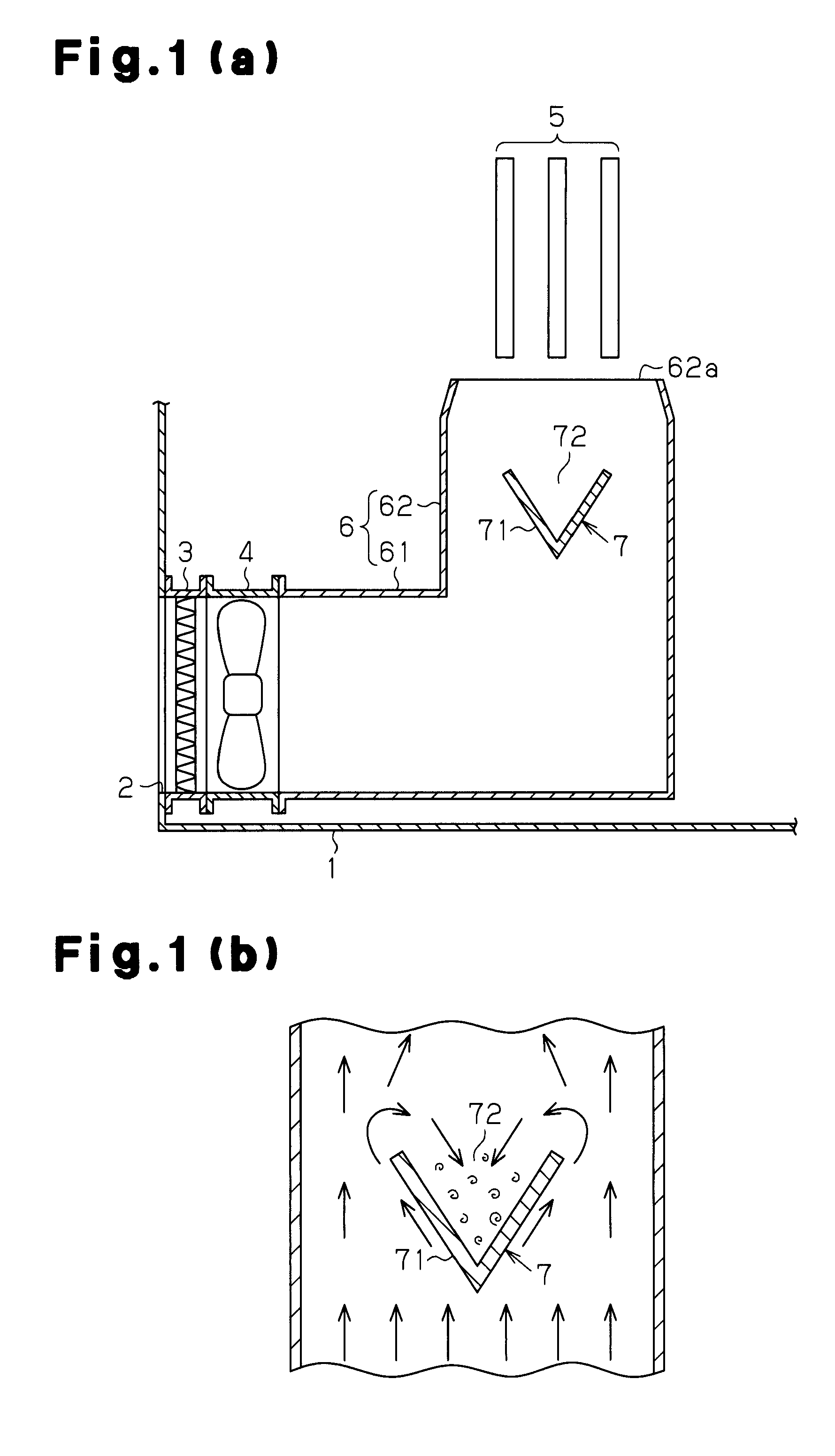
[0022]A video projector according to a first embodiment of the present invention will now be discussed with reference to FIGS. 1(a) and 1(b).

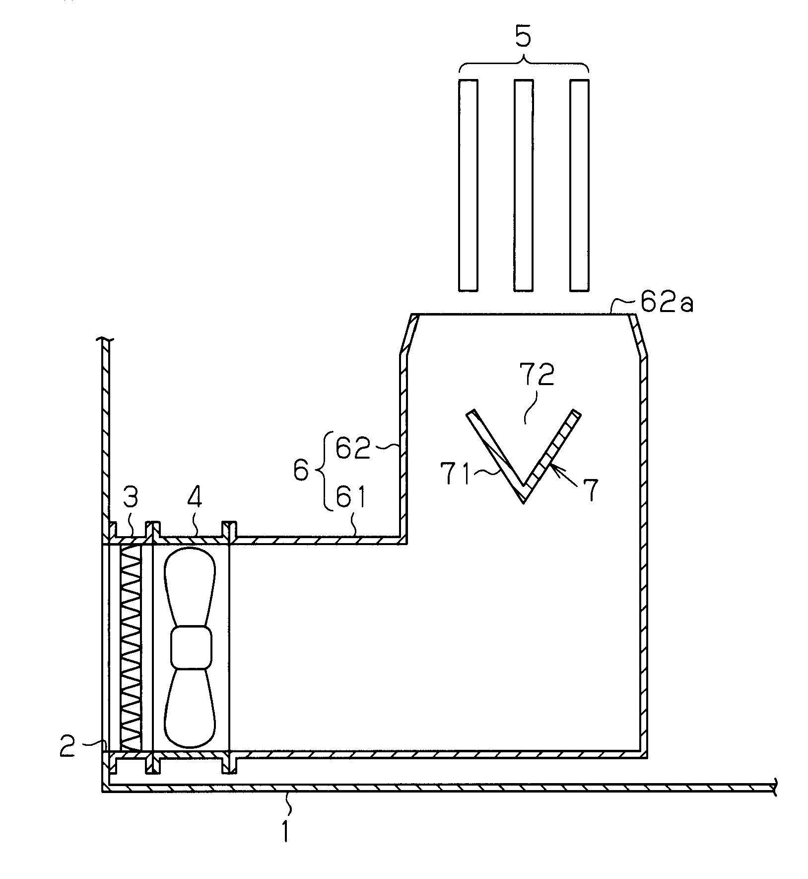
[0023]The video projector may be, for example, a so-called three-chip LCD projector type, which was described above. The video projector includes an optical system, a shell case 1, and a cooling system. The optical system optically modulates illumination light from a light source lamp in accordance with image signals to generate and project image light. The shell case 1 accommodates optical components of the optical system. The cooling system cools the optical components. The cooling system will now be discussed.

[0024]As shown in FIG. 1(a), the shell case 1 includes an air inlet 2. An air filter 3 is arranged in the air inlet 2. An intake fan 4 such as an axial flow fan is arranged at the downstream side of the air filter 3. An intake duct 6 extends from the intake fan 4 to optical components 5, which are to be cooled. The intake duct 6 may be ...

second embodiment

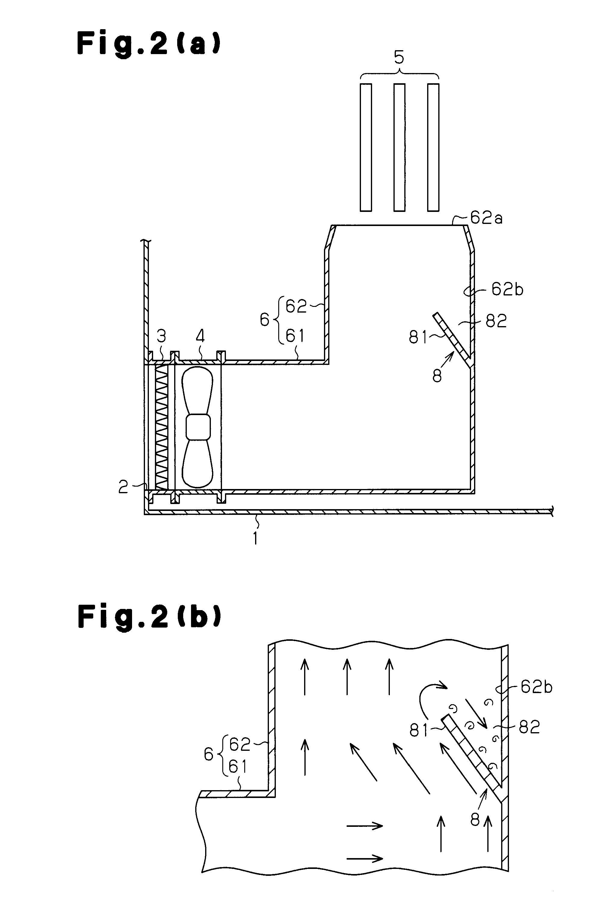
[0033]A video projector according to a second embodiment of the present invention will now be discussed with reference to FIGS. 2(a) and 2(b). In FIGS. 2(a) and 2(b), like or same reference numerals are given to those components that are the same as the corresponding components of the first embodiment. Such components will not be described.

[0034]The video projector of the second embodiment differs from that of the first embodiment in the structure of the turbulent flow generator. Referring to FIG. 2(a), in the second embodiment, a turbulent flow generator 8 includes a projection plate 81 projecting diagonally upward from an inner duct surface 62b in the angled portion 62 of the intake duct 6. The projection plate 81 has a downstream surface that defines a V-shaped pocket 82 in cooperation with the inner duct surface 62b. The diagonal upstream surface of the projection plate 81 changes the direction of the air flow. The pocket 82 has an opening in the downstream direction of the air ...

third embodiment

[0038]A video projector according to a third embodiment of the present invention will now be discussed with reference to FIG. 3. In FIG. 3, like or same reference numerals are given to those components that are the same as the corresponding components of the first embodiment. Such components will not be described.

[0039]The video projector of the third embodiment includes a sink 9, which is a dust-collecting pit arranged at the most distal part of the straight portion 61. Air drifts into the sink 9. The intake duct 6 may be a T-shaped pipe having one closed end. More specifically, the intake duct 6 includes the straight portion 61, which extends straight from the air inlet 2, the angled portion 62, which extends at a generally right angle from the straight portion 61, and the sink 9, which is formed in a corner between the straight portion 61 and the angled portion 62. The sink 9 includes a striking surface 61a facing directly toward the flow of air in the straight portion 61. The an...


PUM


Abstract

A video projector includes a shell case, which accommodates optical components, and a cooling system, which directs ambient air toward the optical components. The cooling system includes a turbulent flow generator arranged in an intake duct. The turbulent flow generator includes a diagonal upstream surface that smoothly changes the direction of an air flow and generates a turbulent flow at the downstream side of the turbulent flow generator. Fine dust particles suspended in the turbulent flow adheres on a downstream surface of the turbulent flow generator and are removed from the air flow.

Description

CROSS-REFERENCE TO RELATED APPLICATIONS[0001]This application is based upon and claims the benefit of priority from prior Japanese Patent Application No. 2009-279465, filed on Dec. 9, 2009, the entire contents of which are incorporated herein by reference.BACKGROUND OF THE INVENTION[0002]The present invention relates to a video projector, and more particularly, to a cooling mechanism for an optical component that optically modulates illumination light from a light source lamp to generate image light.[0003]In the prior art, a so-called three-chip LCD projector includes dichroic mirrors and three liquid crystal panels. The dichroic mirrors separate the light emitted from a light source into red, green, and blue light, which are the three primary colors. The liquid crystal panels combine colored light, which have been optically modulated in accordance with an image signal for each color, and projects an enlarged color image through a projection lens. In such a video projector, an optic...

Claims


Application Information

Patent Timeline
Patent Type & Authority Applications(United States)
IPC IPC(8): H04N5/74
CPCH04N9/3144G03B21/16
Inventor MINAMI, KAZUYA
Owner SANYO ELECTRIC CO LTD
Why Eureka
Try Eureka