Dynamic illumination control for laser projection display

a technology of dynamic illumination control and laser projection display, which is applied in the field of dynamic illumination control of laser projection display, can solve the problems of difficult to increase c/r, add significantly to the cost of the projection system, and the mechanical iris of the '314 disclosure must be a high-speed device, so as to reduce the stray light on the screen, improve image contrast, and eliminate hysteresis

Inactive Publication Date: 2011-06-09
EASTMAN KODAK CO
View PDF27 Cites 11 Cited by
  • Summary
  • Abstract
  • Description
  • Claims
  • Application Information

AI Technical Summary

Benefits of technology

[0021]It is an advantage of the present invention that it provides an adaptive method and apparatus for improving image contrast in a digital image projector.
[0022]With linear and area light modulators, light attenuation is combined with laser blanking, synchronized to the scan to minimize stray light on screen from light passing through the optics when the lasers are off the screen. For example, during this time period, when a GEMS device is used, the charge applied to the substrate may be flipped to eliminate hysteresis. Laser blanking minimizes the stray light which occurs during the substrate flipping. The laser blanking can be accomplished by either switching the laser off or using an electrooptic modulation device.
[0023]The use of an electro-optic modulation device, such as an LC optical shutter, allows both laser blanking and dynamic illumination control. When an image has a low maximum code value, the contrast of the image can be enhanced by making the blacks appear blacker and boosting the delivered code values of the image proportionally by the amount of attenuation. Also, the modulation device can be segmented so that different regions on the screen can have different amounts of attenuation. This is useful for scenes in which bright areas exist such as sun-filled sky towards the upper parts of the image and dark details at the bottom of the image. As an example, if the maximum intensity of a scene is only 10% of the maximum, code values in the image can be adjusted by a 10× range and the attenuator can be set for 10× attenuation. This can increase the contrast significantly.

Problems solved by technology

In general it is difficult to increase C / R by increasing the white luminance of the projection system since most projectors are light source limited.
The mechanical iris of the '314 disclosure must be a high-speed device and can be relatively costly.
The specialized display screen taught in the '332 disclosure adds significantly to projection system cost and may not be a suitable solution where it is desirable to replace existing film projection equipment.
However, there are a number of limitations inherent to linear spatial light modulators that can tend to constrain projector performance.
A number of limitations relate to the scanning sequence itself.
Thus, light output is not available during about 15-25% of the operating cycle, since the mirror requires some amount of time to stop, reverse direction, and return back into position for the next scan.
This inherent reduction of the available light output limits the light efficiencies that can be obtained.
Another problem related resulting from the scanning sequence relates to the need to minimize the effects of stored charge as the ribbon elements are repeatedly switched between positions.
Usually the voltage is switched during the reset interval of the scanning mirror and stray light can reach the screen when the voltage is switched, thus degrading system contrast.
A small amount of light is also inadvertently directed into the optical system during this transient which can result in extra reflections and stray light passing through the projection optics reaching the display screen.
All of these factors can degrade system contrast.
However, both area and linear light-modulating devices have a refresh cycle, during which unmodulated light can be inadvertently directed to the display surface.
While the laser itself could be momentarily turned off to eliminate stray light during the refresh cycle, such a mode of operation is not optimal for existing semiconductor laser devices, compromising wavelength and thermal stability and potentially shortening laser lifetimes.
Related to the problem of image contrast is the relative distribution of data values over portions of the image.
Stated differently, such images exhibit a high percentage of relatively indistinguishable dark values or “dark noise.” Because there is little difference in contrast over such an area, many features within the image are effectively lost.

Method used


Image

  • Dynamic illumination control for laser projection display
  • Dynamic illumination control for laser projection display
  • Dynamic illumination control for laser projection display

Examples


Embodiment Construction

[0048]The present description is directed in particular to elements forming part of, or cooperating more directly with, apparatus in accordance with the invention. It is to be understood that elements not specifically shown or described may take various forms well known to those skilled in the art. Figures shown and described herein are provided in order to illustrate key principles of operation of the present invention and are not drawn with intent to show actual size or scale. Some exaggeration may be necessary in order to emphasize relative spatial relationships or principles of operation.

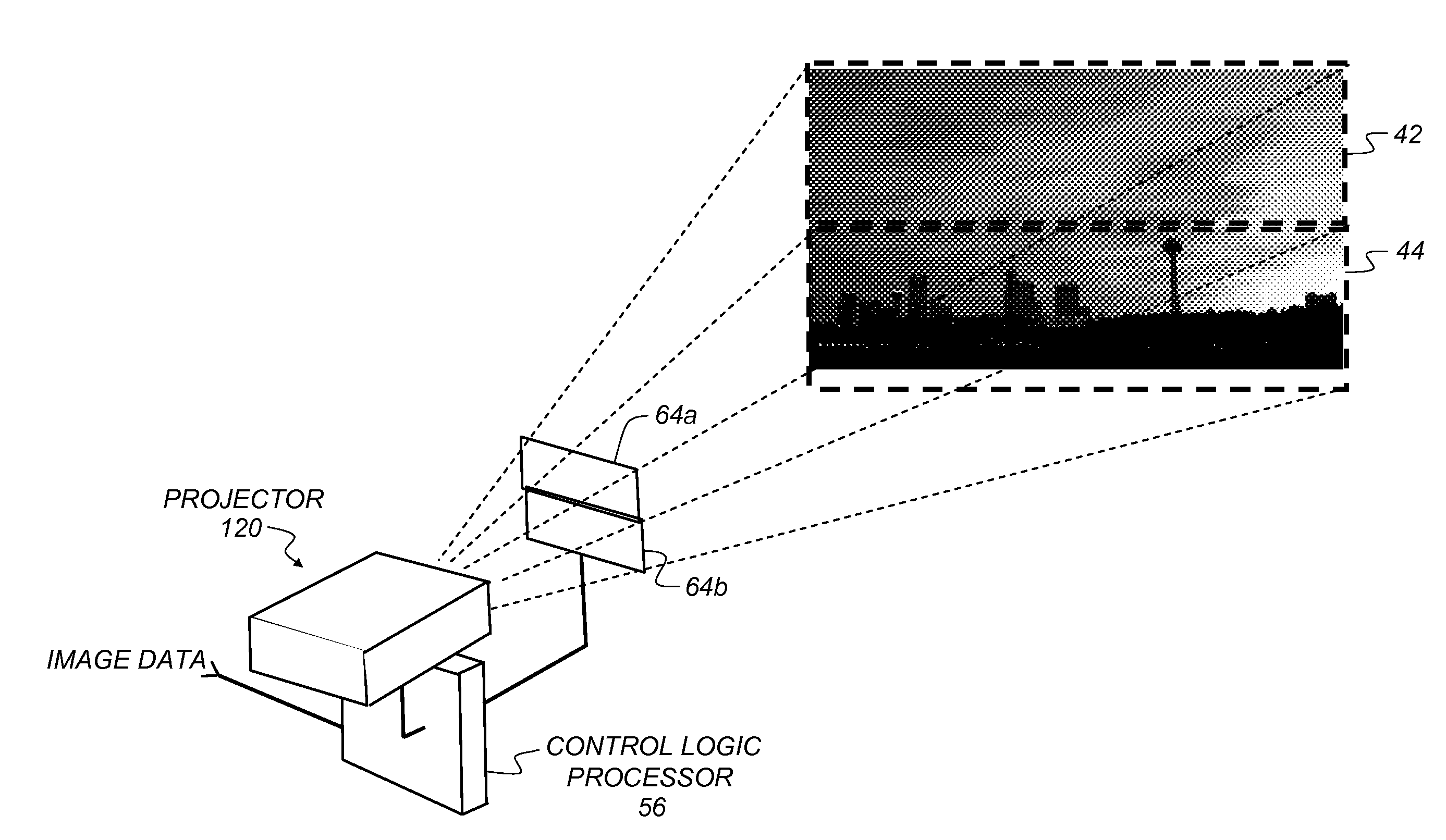
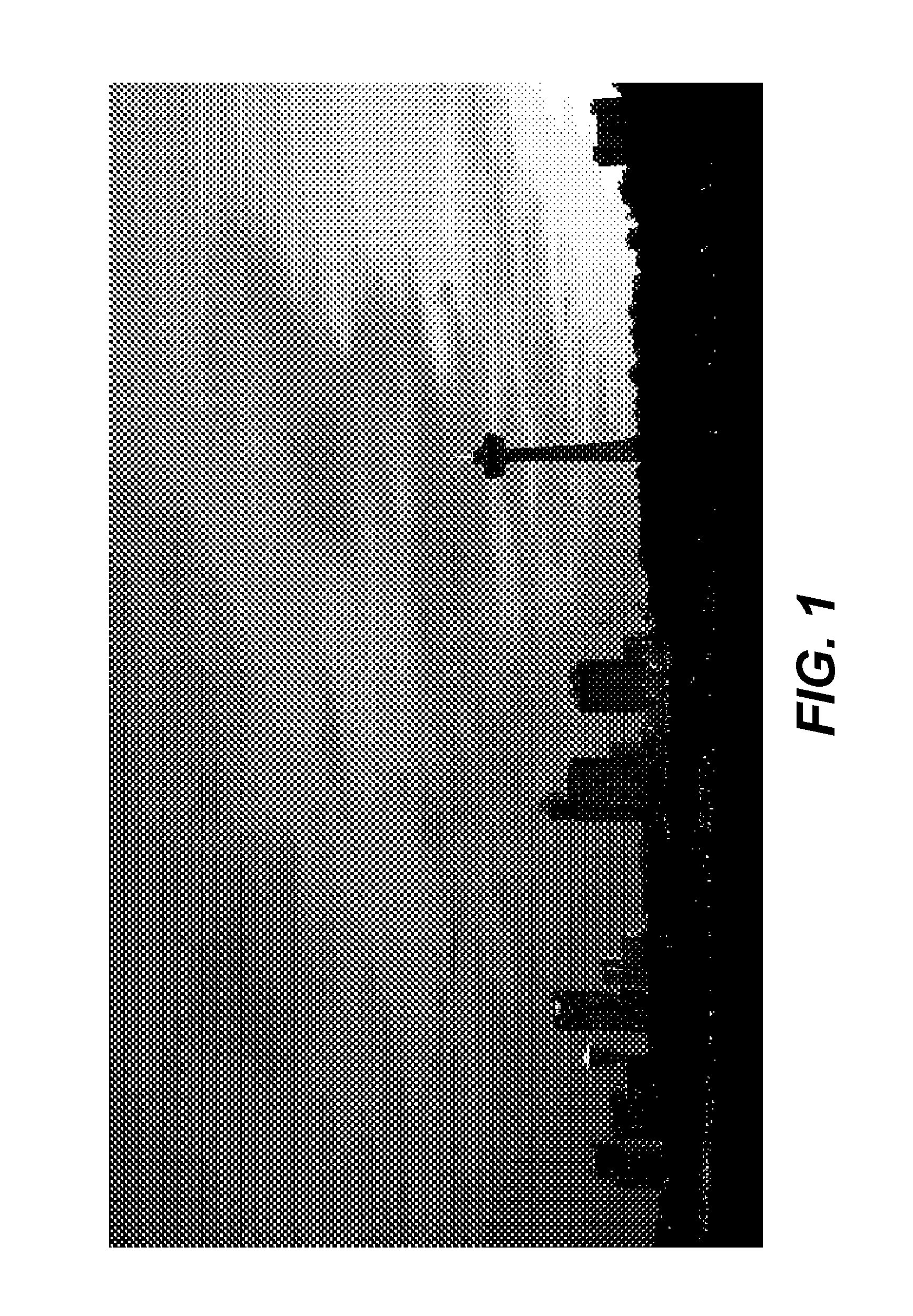
[0049]In the context of the present invention, a “dark region” in an image frame is an area of the image frame that contains a substantial number of pixels below a given threshold code value for darkness within an image. The definition of what constitutes a dark region in any particular case depends on a number of factors, including the type of imaging system and its data representation scheme, ...


PUM


Abstract

A method for improving image contrast for a display apparatus obtains a frame of image data having one or more code values for each pixel in the frame of image data, analyzes the frame of image data to identify a distribution of dark regions therein. The method further adjusts at least one of the one or more code values for the frame of image data according to the distribution of dark regions in the frame of image data and attenuates a brightness level available for the image frame according to the distribution of dark regions in the frame of image data.

Description

CROSS REFERENCE TO RELATED APPLICATIONS[0001]Reference is made to commonly-assigned copending U.S. patent application Ser. No. 12 / 484,374, filed Jun. 15, 2009, entitled DYNAMIC ILLUMINATION CONTROL FOR LASER PROJECTION DISPLAY, by Marcus et al., the disclosure of which is incorporated herein.FIELD OF THE INVENTION[0002]The present invention relates to electronic display apparatus using spatial light modulators and more particularly relates to apparatus and methods for improved contrast and dynamic range in an electronic projection system.BACKGROUND OF THE INVENTION[0003]A critical performance measure in image projection systems is the contrast ratio (C / R) which represents the light intensity difference between the brightest white and the darkest black. C / R is thus defined by the relationship:C / R=white luminance / black luminance  (1).Improving the C / R helps to provide better on-screen image reproduction.[0004]In general it is difficult to increase C / R by increasing the white luminance...

Claims


Application Information

Patent Timeline
Patent Type & Authority Applications(United States)
IPC IPC(8): H04N5/74G06K9/40G06K9/00
CPCH04N9/3182H04N9/3105
Inventor MARCUS, MICHAEL A.AGOSTINELLI, JOHN A.PHALEN, JAMES G.KOWARZ, MAREK W.
Owner EASTMAN KODAK CO
Why Eureka
Try Eureka