Chiral liquid crystal polymer marking
- Summary
- Abstract
- Description
- Claims
- Application Information
AI Technical Summary
Benefits of technology
Problems solved by technology
Method used
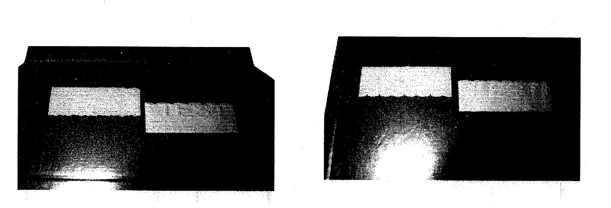
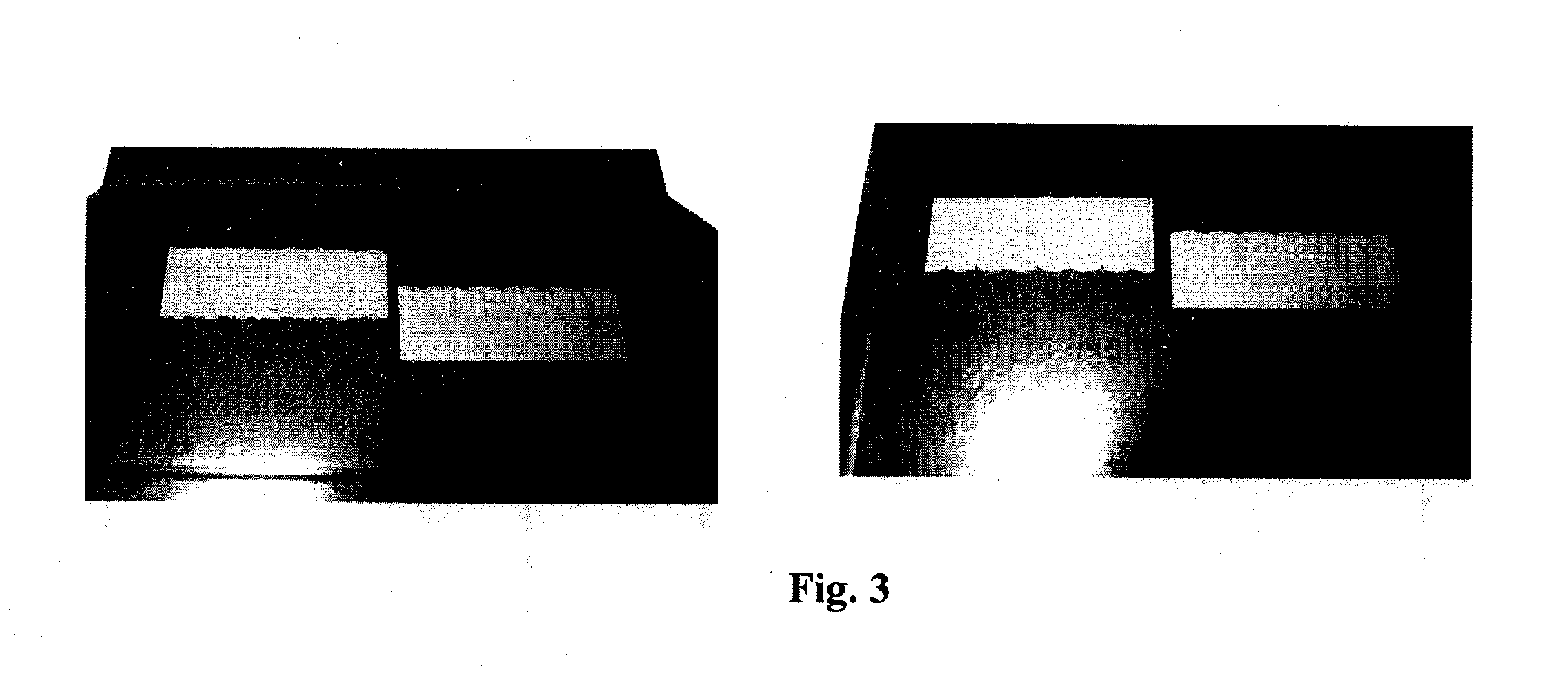
Image

Examples
example
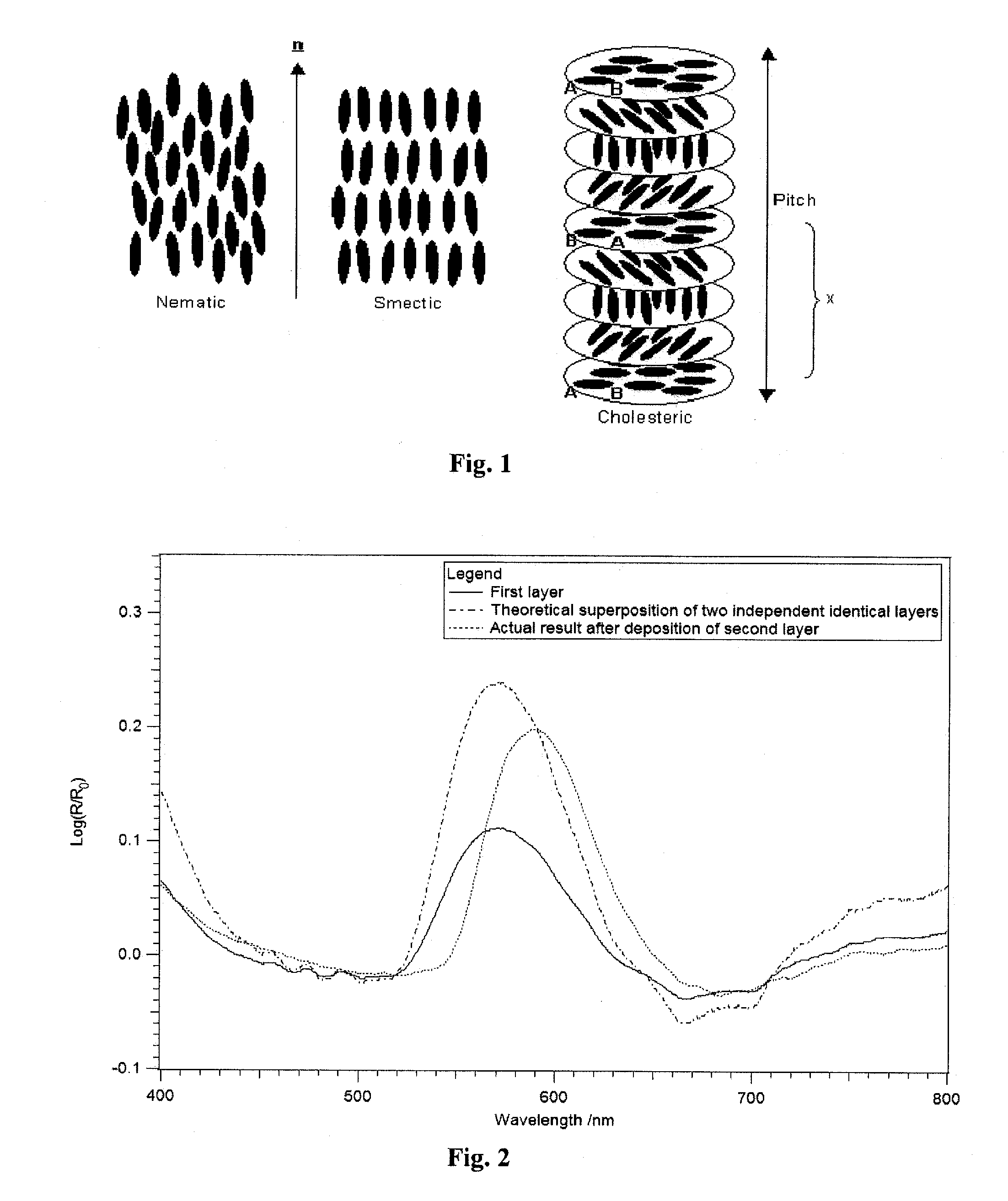
[0103]A marking according to the present invention is prepared as follows:
(1) Preparation of the First Chiral Liquid Crystal Precursors Composition
[0104]A chiral liquid crystal precursor composition (1) was prepared as follows:
A chiral dopant compound B of formula (I) shown above, i.e., (3R,3aR,6R,6aR)-hexahydrofuro[3,2-b]furan-3,6-diyl bis(4-(4-(acryloyloxy)-3-methoxybenzoyloxy)-3-methoxy-benzoate) (7.5 g), a nematic compound A1, i.e., benzoic acid, 4-[[[4-[(1-oxo-2-propen-1-yl)oxy]butoxy]carbonyl]oxy]-1,1′-(2-methyl-1,4-phenylene) ester (22.0 g), a nematic compound A2, i.e., 2-methyl-1,4-phenylene bis(4-(4-(acryloyloxy)butoxy)-benzoate) (14.0 g), and acetone (49.9 g) were weighed into a screwable flask which was thereafter heated in an oven until obtaining a brownish solution. To the mixture were then added tetrabutylammonium perchlorate (0.6 g), lithium perchlorate (0.3 g), 2-methyl-1[4-(methylthio)phenyl]-2-morpholinopropan-1-one (Irgacure 907® from Ciba, 1.3 g), 2,4-diethyl-thi...
PUM
| Property | Measurement | Unit |
|---|---|---|
| Temperature | aaaaa | aaaaa |
| Temperature | aaaaa | aaaaa |
| Time | aaaaa | aaaaa |
Abstract
Description
Claims
Application Information
 - R&D Engineer
- R&D Manager
- IP Professional
- Industry Leading Data Capabilities
- Powerful AI technology
- Patent DNA Extraction
Browse by: Latest US Patents, China's latest patents, Technical Efficacy Thesaurus, Application Domain, Technology Topic.
© 2024 PatSnap. All rights reserved.Legal|Privacy policy|Modern Slavery Act Transparency Statement|Sitemap