Devices and methods for treating vascular malformations

a technology for vascular malformations and devices, applied in the field of abnormalities, can solve the problems of reducing the treatment effect, so as to achieve faster or slower leakage

a technology for vascular malformations and devices, applied in the field of abnormalities, can solve the problems of reducing the treatment effect, so as to achieve faster or slower leakage

US20110137332A1Inactive Publication Date: 2011-06-09STRYKER CORP

Image

  • Devices and methods for treating vascular malformations
  • Devices and methods for treating vascular malformations
  • Devices and methods for treating vascular malformations

Examples


Embodiment Construction

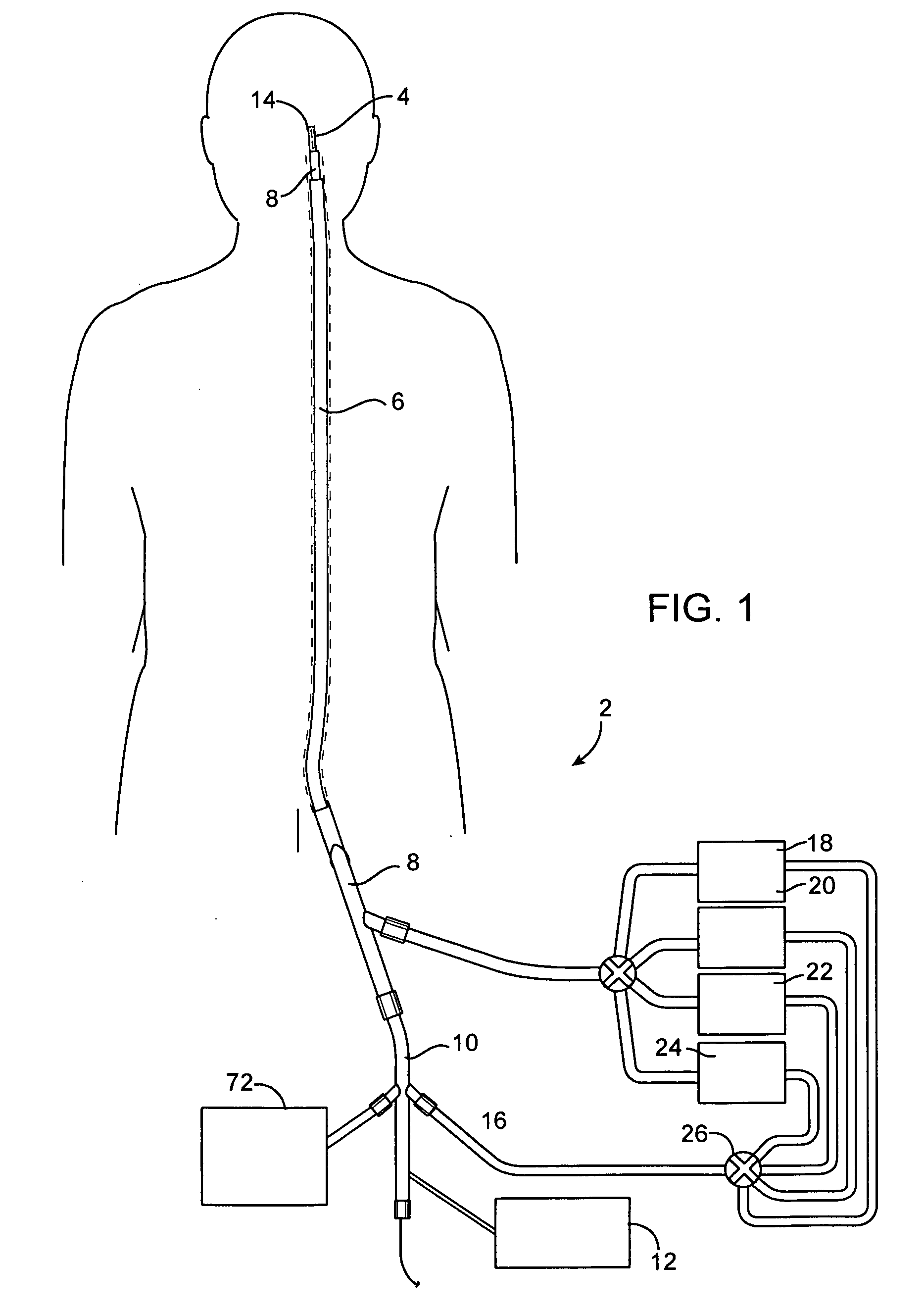
[0108]Referring to FIG. 1, a system 2 for introducing an expandable device 4 into a cerebral aneurysm is shown. A first catheter 6 extends through a penetration in the femoral artery and up to the carotid artery. A second catheter 8 is advanced through the first catheter 6 and into the cerebral vasculature to the site of the aneurysm or other abnormality. A delivery catheter 10 is then advanced through the second catheter 8. The catheter 10 delivers an expandable device 4 which partially fills the aneurysm as will be described below. The system 2 also has an energy supply 12 for heating the aneurysm to shrink the aneurysm as will be described below.

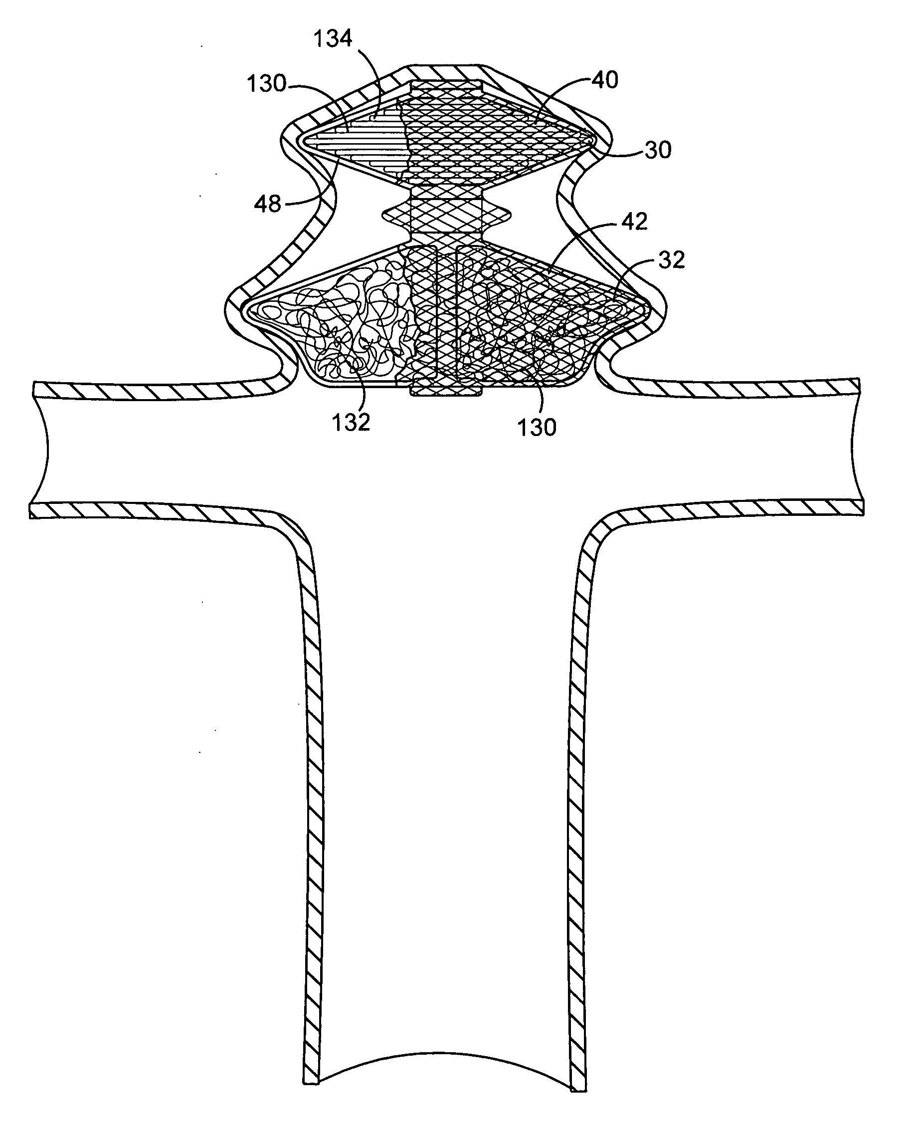
[0109]After the expandable device 4 has been delivered to the aneurysm and expanded, the aneurysm is reduced in size as shown in FIG. 6. The aneurysm may be shrunk partially toward the expandable device 4, into engagement with the expandable device 4, or may even be shrunk until the expandable device 4 is also reduced in size. An advantag...


PUM

PropertyMeasurementUnit
diameteraaaaaaaaaa
temperatureaaaaaaaaaa

Abstract

A device for treating vascular malformations includes a primary coil and secondary windings. The primary coil provides resilience and structural integrity while the secondary windings fill interstitial spaces in the primary coil to isolate the vascular malformation. The device may have increased density along a central portion to isolate the malformation. In another aspect, the device may have a central opening through which embolic materials may be delivered.

Description

CROSS-REFERENCES TO RELATED APPLICATIONS[0001]The present application is a continuation in part of U.S. patent application Ser. No. 09 / 695,637, filed Oct. 24, 2000, which is a continuation in part of application Ser. No. 09 / 324,359 filed Jun. 2, 1999, which are hereby incorporated herein by reference. The application is also related to U.S. patent application Ser. No. ______, filed on Mar. 25, 2002, entitled “Containers and Methods for Delivering Vaso-occluding Filaments” by inventors Dieck et al. and U.S. Provisional Application Ser. Nos. 60 / 288,458, 60 / 288,467, 60 / 288,459, 60 / 288,494 and 60 / 330,619 which are also hereby incorporated by reference.BACKGROUND OF THE INVENTION[0002]The present invention relates to treatment of abnormalities in a patient's vascular system. A specific use of the present invention described below is for the treatment of cerebral aneurysms although the various aspects of the invention described below may also be useful in treating other abnormalities such...

Claims


Application Information

Patent Timeline
09 Jun 2011
Publication
US20110137332A1
IPC
A61M29/00; A61B17/00; A61B17/12; A61B18/14; A61F2/958; A61L24/00; A61L24/04; A61L24/10; A61L31/04; A61L31/10; A61L31/14; A61L31/16; A61M25/00
CPC
A61B17/12022; A61B2017/12095; A61B17/12118; A61B17/12136; A61B17/12145; A61B17/12172; A61B17/12186; A61B17/1219
Inventors
SEPETKA, IVAN; DIECK, MARTIN S.